Build AirSense: an ESP32 air purifier that proves what it filters
AirSense pairs a Xiaomi HEPA filter and 150 mm fan with an ESP32-S3, live PM2.5/AQI telemetry, public CAD, and a weekend-sized but mains-aware build challenge.

The pick
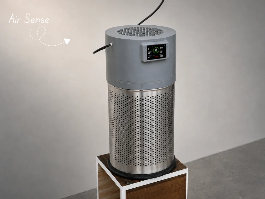
AirSense is an ESP32-S3 air purifier that measures the air after it has passed through a HEPA filter. It combines a Xiaomi Air Purifier 4 Lite filter, a 150 mm fan, a perforated 18 L metal bin, a small LCD, and environmental sensors into one enclosure. The unusual bit is not the fan; it is the feedback loop. You can see PM2.5, AQI, temperature, humidity, and pressure locally, then switch the fan from an Arduino IoT Cloud dashboard. 1
Hackaday published its feature on July 21, 2026, inside this week’s window. The project’s companion build guide is unusually actionable: 33 steps, downloadable STL parts, a connection diagram, and an Arduino sketch are all public. 2 3
Weekend verdict: worth building if you already have a 3D printer, can work safely around mains wiring, and want a measurable air-quality project rather than a decorative IoT gadget. It is not a beginner soldering project: the build is mechanically involved, and the fan is switched at wall voltage.
What makes it stand out
Most DIY air purifiers stop at “fan plus filter.” AirSense places its dust and environmental sensors in the exhaust path, so the display and dashboard report the air leaving the machine rather than only the room around it. Hackaday describes the enclosure as a cylindrical Xiaomi filter inside a perforated metal bin, with the 150 mm exhaust fan mounted in a 3D-printed top cap. 1
The project is also more reproducible than a one-off build log. The repository has STL files for the housing, motor mount, filter base, bottom plate, gasket seal, and display cover, plus a PNG connection diagram and the
Airsense.ino firmware. 3There is one important limit to the project’s claims: the author does not publish a measured clean-air delivery rate or a controlled sensor validation. Treat the displayed AQI and PM2.5 values as useful project telemetry, not as a calibrated indoor-air instrument.
BOM and budget
The original guide names the parts below but does not publish a single priced BOM. The ranges are a planning estimate for one build in USD, before tax, shipping, and the 3D printer. The two price anchors that are easy to verify are the ESP32-S3 board (Waveshare lists compatible boards around $10–16) and the Waveshare dust sensor ($13.99 on its product page); fan, filter, and bin prices vary much more by country and seller. 4 5
| Qty | Part | What the guide specifies | Estimated cost |
|---|---|---|---|
| 1 | Waveshare ESP32-S3 development board | Controller; select an ESP32-S3 board compatible with the guide’s pin map | $10–16 |
| 1 | Waveshare 2.4-inch LCD module | 320×240 ILI9341 SPI display | $6–15 |
| 1 | Waveshare Dust Sensor | Analog PM/dust sensor | $14 |
| 1 | Waveshare BME680 environmental sensor | Temperature, humidity, pressure, and gas readings over I²C | $8–15 |
| 1 | Digital 10 A relay module | Switches the fan control path | $2–6 |
| 1 | 5 V, 2 A power adapter | Low-voltage supply for the controller and modules | $8–15 |
| 1 | Xiaomi Smart Air Purifier 4 Lite filter | Cylindrical filter element; the guide cites 99.97% capture of 0.3 μm particles | $25–40 |
| 1 | Anchor Smart Air 150 mm ventilation fan | Exhaust fan mounted in the printed cap | $20–50 |
| 1 | 18 L perforated stainless open-top bin | Main enclosure | $10–25 |
| 1 set | Printed mechanical parts | Housing, motor mount, filter base, bottom plate, gasket seal, and display cover | $5–20 in filament |
| as needed | Wire, solder, fasteners, strain relief, and mains-rated enclosure hardware | The guide lists tools but does not give quantities for these consumables | $5–15 |
That puts the working total at roughly $115–230, with shipping and the printer excluded. The low end assumes inexpensive generic mechanical parts; the high end is more realistic if the specified fan and filter are bought locally. This is an editorial estimate, not a price quoted by the author. The source list and the complete step sequence are in the AirSense guide. 2
Circuit and enclosure overview
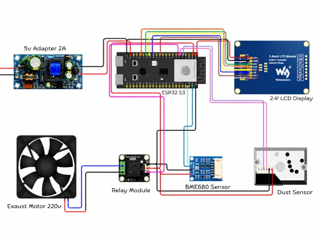
The low-voltage wiring is straightforward:
- The LCD uses SPI: DIN GPIO11, CLK GPIO12, CS GPIO10, DC GPIO9, RST GPIO8, with 3.3 V for VCC and backlight.
- The BME680 uses I²C on SDA GPIO43 and SCL GPIO44.
- The dust sensor uses GPIO5 for its LED-control input and GPIO6 for analog output.
- The relay signal is on GPIO7.
The firmware samples the BME680 and dust sensor every two seconds, refreshes the display, calculates an AQI value, and synchronizes
DUST, Temperature, Humidity, and AQI to the cloud. The fan’s Power variable is read/write, so the dashboard can turn the relay on or off. 7The mains side is the part that changes the project’s risk profile: wall live goes to relay COM, relay NO goes to the fan live lead, and wall neutral goes directly to fan neutral. That is the topology shown in the guide, not a recommendation to prototype it on a breadboard. Work de-energized, use a properly rated relay, cable entry, insulation, strain relief, and enclosure, and have a qualified person inspect the mains section if you are not already comfortable with line-voltage wiring. 2
The mechanical side is the real design contribution: the fan is adapted to the printed motor mount and cap, the filter sits on a printed base inside the perforated bin, and the gasket seals the filter path. The repository’s CAD Design folder contains the STL files; print time and material choice will determine whether this fits into one weekend.
Firmware and software
The public
Airsense.ino sketch targets an ESP32S3 Dev Module. The guide calls for USB CDC on boot, QIO 80 MHz flash, 4 MB flash, the Huge APP partition, disabled PSRAM, and a 921600 upload speed. It also asks the builder to install and configure:TFT_eSPILVGLAdafruit BME680ArduinoIoTCloudArduino_ConnectionHandler
The repository code uses Arduino IoT Cloud and updates the display and cloud state continuously, with sensor values refreshed every two seconds. You will need an Arduino Cloud Thing, device credentials, and your own Wi-Fi details. Do not copy credentials from a public sketch into your build; replace them with your own values and audit any fork before publishing it. 7
One practical catch is the library configuration. The guide calls for replacing
TFT_eSPI/User_Setup.h and adding lv_conf.h, so “compile the sketch” is not the whole software task. The dashboard also uses five cloud variables: read-only AQI, dust, temperature, and humidity values, plus a read/write fan-power switch. 2Reproduction difficulty: advanced
Rating: Advanced. Budget a full weekend of hands-on work, plus printer time, if every part is already on the bench. That estimate is mine, not the author’s.
Why it lands above intermediate:
- You must modify and mount a fan, print and fit several structural parts, and seal the filter path.
- The relay switches mains voltage. A mistake can cause shock, fire, or equipment damage; this is not a safe first mains project.
- The software stack spans ESP32 board settings,
TFT_eSPIand LVGL configuration, Arduino IoT Cloud provisioning, and sensor/display pin mapping. - The source does not provide a fully priced BOM or a calibration procedure, so expect to validate readings yourself rather than treating the first numbers on the LCD as laboratory data.
The minimum sensible tool bench is a soldering iron, solder, pliers, screwdrivers, a 3D printer, a multimeter, and safe mains-work equipment. The original guide explicitly lists the first four and the printed parts; the multimeter and mains safety gear are prudent additions for a build that contains a relay-controlled AC fan.
Should you build it this weekend?
Build AirSense if you want a substantial enclosure-and-firmware project with a clear sensor story and public files. Skip it if you need a quick, low-risk soldering win, if you do not already have a printer, or if the fan and filter are not available locally.
The project has some public traction—at the time of checking, the Hackaday feature showed 24 comments and the GitHub repository showed 5 stars and 2 forks—but those are attention signals, not independent proof that the complete build has been reproduced. 1 3
If you do proceed, start with the CAD prints and a dry fit of the filter, bin, cap, and fan before soldering. Then bring up the ESP32, display, and sensors on the bench; only after the low-voltage readings and relay logic behave as expected should the mains section be closed inside its enclosure.
相似内容
- 登录后可发表评论。