Falkirk Wheel — how a rotating boat lift solved a 35-metre problem on 1.5 kWh

Falkirk Wheel — how a rotating boat lift solved a 35-metre problem on 1.5 kWh

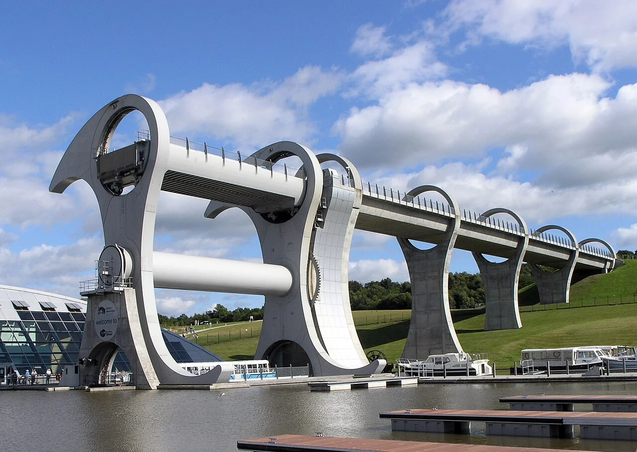
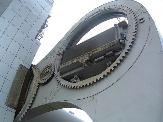
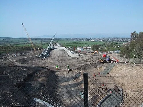
A 5,075-word engineering case study tracing every design decision in the Falkirk Wheel (2002) back to the Archimedes balancing principle. Covers: the Millennium Commission brief and why rebuilding the 11-lock Falkirk Flight was rejected; the three-week RMJM/Arup concept sprint and Lego-brick demonstration; the epicyclic planetary gear train that keeps gondolas horizontal; the six-step docking sequence with subsea-pipeline hydraulic coupling; the 14,000-bolt bolted-not-welded structural choice for 120-year fatigue life; Butterley Engineering pre-assembly in Derbyshire and 35-lorry transport; the Rough Castle Tunnel modified road-planer technique; and the current infrastructure middle age — £2.7M 2023/24 refurbishment and Falkirk Flight lock gate replacement (August 2026 reopening).

Engineering Marvel Teardown
June 1, 2026 · 11:26 PM
4 subscriptions · 15 items
On a Tuesday morning in central Scotland, a narrowboat loaded with two adults and a full water tank eases into a steel gondola the size of a shipping container. A sequence of mechanical events follows — pins extend, a hydraulic lance docks, a U-shaped seal telescopes across a gap, water floods in to equalise pressure, and two vertical doors lower. The gondola is now sealed. Three minutes later the entire 1,800-tonne rotating wheel has turned 180 degrees, the gondola is at the other end, and the boat is 24 metres higher than it started. The energy consumed — about 1.5 kilowatt-hours — would boil eight kettles of water. 1
That number is the engineering story. Every structural decision, every gear ratio, every decision to bolt rather than weld, traces back to a single insight that the design team locked in early: if you keep both gondolas exactly balanced at all times, the energy required to rotate them approaches zero. The Falkirk Wheel, opened in May 2002 and still the only rotating boat lift in the world, is a machine built around one physical principle stretched across many engineering disciplines simultaneously.

The problem: 35 metres and a canal system that went dead

The Forth and Clyde Canal, completed in 1790, runs east–west across Scotland's Central Belt, connecting the Firth of Forth near Edinburgh with the Clyde estuary near Glasgow. The Union Canal, built in 1822, extends that connection eastward to Edinburgh itself, but at a different elevation. At Falkirk, the Union Canal sits 35 metres (115 ft) above the Forth and Clyde Canal. 1
For 143 years, from 1822 to 1933, that height difference was handled by the Falkirk Flight: eleven locks arranged in a staircase pattern along the hillside at Port Downie. Eleven locks meant eleven lockfuls of water consumed per passage — approximately 3,500 tonnes each time a boat made the full transit. 2 It also meant that a transit took the better part of a day. By the time commercial barge traffic on the Scottish canals had been killed off by the railways, the locks were no longer worth maintaining. British Waterways demolished the flight in 1933. 1 By the 1960s both canals had fallen into dereliction.
The specific nature of that dereliction matters to understanding the brief that followed. These were not remote wilderness waterways. They passed through communities across Scotland's Central Belt — Falkirk, Grangemouth, Glasgow's northern suburbs — that had grown up alongside them and then watched them choked with vegetation and used mainly as informal dumping grounds. When revival came, it would carry social and symbolic weight alongside the engineering.
In 1994, British Waterways Board announced it would bid for funding under the UK Millennium Commission's national programme for projects marking the year 2000. The formal application went in the following year. On 14 February 1997, the Commission awarded £32 million — 42% of the original £78 million project cost — to the Millennium Link, the most extensive canal restoration project in British history. 1 The total programme budget eventually rose to £84.5 million, of which the Wheel and its associated basin was priced at £17 million. 3
The simplest response to the height problem was the obvious one: rebuild the eleven locks. British Waterways rejected that option not because it was technically impossible, but because it would not be the centrepiece a Millennium project required. A working lock flight, however competently reconstructed, is functionally invisible. Locks have been operating on British canals since the 17th century. What the project needed, in the words of the brief, was a landmark for the 21st century.

From Ferris wheel to Celtic axe: the design that won

The first design submission did not win that argument. A joint venture called Morrison–Bachy Soletanche proposed a structure resembling a Ferris wheel with four gondolas. The mechanism worked. Engineers confirmed it would move boats reliably. But British Waterways' client team looked at the renderings and saw a piece of industrial equipment, not a public statement. They wanted something that would draw people who had no interest in boating whatsoever — a landmark that would make Falkirk a destination. 1
In summer 1999, a 20-person team of architects and engineers assembled under the leadership of Tony Kettle, a lead architect at RMJM. The core engineering consultancy was Arup; fabrication would be handled by Butterley Engineering of Ripley, Derbyshire, with structural input from Tony Gee and Partners. 1 The group had three weeks to produce a concept that could be presented to funders.
The story of how the mechanism was explained to non-engineers during that sprint has become one of the project's most-retold details: Kettle demonstrated the gear system using his eight-year-old daughter's Lego bricks. 1 The model was crude, but it conveyed the counterintuitive key point — that a rotating structure could keep horizontal containers horizontal throughout the full rotation — in under a minute. That was the insight clients needed to sign off on the concept.
The visual language drew from several sources. Kettle later described the finished form as "a beautiful, organic flowing thing, like the spine of a fish" 2 — but the design process referenced more specifically a double-headed Celtic axe, the propeller of a ship, and the ribcage of a whale. The curved axe arms that extend from the central hub, each reaching 15 metres beyond the axle, carry both the structural load and the visual identity. The Royal Fine Art Commission for Scotland called the result "a form of contemporary sculpture." 1
The site presented its own complications before anyone drew a structural plan. The ground at Port Downie was not clean earth. The area had been used as an open-cast fireclay mine, a coal mine, and a tar works; soil samples came back contaminated with tar and mercury. The upper 20 metres was loose backfill — far too weak to take the loads of a 1,800-tonne rotating structure. The solution was 30 concrete piles, each 22 metres deep, bored through the contaminated overburden and socketed into bedrock. 1

The Archimedes trick: why the weight of boats doesn't matter

The critical insight that determines the Wheel's energy consumption is almost counterintuitive at first encounter, and it derives entirely from Archimedes' principle applied to a floating body.
Each of the two gondolas holds 250,000 litres (55,000 imperial gallons) of water. 1 Each gondola weighs 50 tonnes empty. When operating, the total weight of a loaded gondola — water plus any boats floating in it — is always the same. A narrowboat displaces its own weight in water. When a 20-tonne boat enters a gondola, it pushes out exactly 20 tonnes of water; the total mass of (gondola + water + boat) does not change. The system doesn't "feel" the boat at all.
The result is that the two gondolas, mounted on diametrically opposite ends of the wheel's arms, always weigh the same as each other — approximately 300 tonnes each (water plus empty gondola), regardless of whether they carry zero, one, or four canal boats. The wheel is not fighting an imbalance. It is rotating a perfectly balanced pair of counterweights. As Grady Hillhouse of Practical Engineering put it: "Part of the engineering genius of the Falkirk Wheel is that it's always balanced, whether there are boats inside the gondolas or not." 2
The practical consequence is the energy figure: rotating the balanced structure requires only 1.5 kWh per half-turn — the electrical equivalent of boiling eight kettles. 4 Compare that to the 3,500 tonnes of water consumed by a single passage through the old eleven-lock flight. 2 The locks didn't just take all day; they were hydraulically expensive in a way a balanced rotating mechanism is not.
It is worth pausing on what the 1.5 kWh figure actually means in engineering terms. The structure rotating weighs approximately 1,800 tonnes. The arms span 35 metres. The rotational inertia of that mass is substantial. Yet nearly all of it is balanced — the work the motors perform is almost entirely overcoming bearing friction and accelerating and decelerating the assembly's angular momentum at the start and end of each rotation. The hydraulic drive system is deliberately oversized relative to the steady-state running load precisely to handle those acceleration and deceleration phases smoothly without jerking the water in the gondolas. If the acceleration curve is too aggressive, the water surface tilts, the 37 mm tolerance is breached, and the computer control system has to intervene with the compensating sluices. The slow, controlled rotation visible from the visitor walkway is not leisurely — it is the optimised acceleration profile for keeping the gondola water surfaces flat.
Maintaining this equilibrium in operation required a site-wide computer control system that monitors water levels in both gondolas using sensors and adjusts sluices and pumps to keep the level difference between them within 37 mm (1.5 inches). 1 That is the working tolerance of the balancing principle. Exceed it, and the wheel experiences a net torque. Stay within it, and the 10 hydraulic motors driving the rotation are working against little more than bearing friction, the inertia of the structure, and minor aerodynamic drag.
The ten hydraulic motors deliver a combined 22.5 kW (30.2 hp) — a modest figure for a structure the size of an eight-storey building. Each motor drives through a 100:1 gear reduction; the motors also double as brakes, resisting rotation passively when power is cut. 1 A complete 180-degree rotation takes approximately five minutes. 5 Five minutes, compared to a full day.
Loading content card…

The gear train that keeps gondolas level

Equilibrium solves the energy problem. It does not, by itself, solve the orientation problem. As the wheel rotates, the arms swing through 180 degrees. If the gondolas were simply bolted to the arms, they would rotate with them, and water would pour out of one end and pile up at the other long before the rotation was complete. Keeping each gondola horizontal throughout the full arc required an independent mechanism.
The solution is an epicyclic (planetary) gear train with five gears: three large ring gears, each 8 metres (26 ft) in diameter, alternating with two smaller idler gears. 1 The arrangement exploits the geometry of the structure with precision.
Close-up of the ring gear mechanism at the end of the Falkirk Wheel arm
The 8-metre-diameter ring gears at the end of each arm, driving counter-rotation to keep the gondolas level. 1
The central large ring gear, fitted over the axle at the machine room end, is fixed in place — it does not rotate. The two smaller idler gears are bolted to each of the wheel's arms. When the hydraulic motors rotate the central axle and swing the arms, the idler gears are forced to roll around the fixed central gear, spinning as they go. The idler gears then engage the large ring gears at each gondola end, driving those ring gears at the same angular speed as the arms but in the opposite direction — cancelling the arm rotation exactly. The gondola, attached to its ring gear, stays horizontal. 1
The gear geometry is elegant in principle, but it faced one practical problem that the designers had to engineer around. A rotating structure under variable load deflects. When a 250-tonne gondola of water plus boats sits at the end of a 15-metre arm, those arms bend slightly. If the gear teeth were designed to mesh at a fixed, precise centre distance, structural deflection would cause them to bind or skip under load.
The solution came from an unexpected source: old mechanical clocks. Clock gears use a shallow involute angle — a relatively flat tooth profile that allows the meshing gears to move slightly off-centre without losing proper tooth engagement. 5 Arup's engineers adopted the same shallow involute angle for the Falkirk Wheel's caisson-stabilising gears, giving each gear pair a degree of centre-distance tolerance that accommodates the structural flex of loaded arms without compromising the horizontal-keeping function. A design principle from 17th-century watchmaking was necessary to make a 21st-century canal lift work correctly.
The drive system at the axle ends is more complex still. Pairs of 4-metre-diameter three-row slewing bearings are fitted at each end of the central axle. The outer bearing rings are bolted to the fixed support structure; the inner rings — carrying internal gear teeth — are bolted to the tubular axle itself. A gearbox inside the axle meshes with these internal teeth. 5 The hydraulic motors are housed in a machine room inside the final pillar of the aqueduct, spread across seven chambers connected by ladders: ground floor holds the 11 kV transformers, first floor the standby generator and switchgear, second floor the hydraulic pumps.
The complete drivetrain — from the 11 kV supply through the transformers, hydraulic pumps, motors, slewing bearings, axle gearbox, fixed central gear, idler gears, and gondola ring gears — is a cascading system in which every stage was sized against the requirement that the whole thing consume barely more energy than a domestic appliance.

The docking dance: sealing a moving structure to a static canal

Archimedes keeps the wheel balanced. The gear train keeps the gondolas level. The third distinct engineering problem is the one visitors actually watch happen: connecting a gondola in motion to a static canal without letting the water drain away.
Each gondola's ends carry vertically rising hinged doors. The rising design was chosen specifically over conventional side-hinged doors: a hinged door needs to swing into the gondola's usable length, eating into the space available for boats. A door that rises vertically from a recess in the gondola floor takes no usable length at all. 1 When a gondola is out on the rotating structure, these doors are sealed against the water inside.
The docking sequence has six distinct steps, each dependent on the previous one completing cleanly:
  1. The wheel stops with the arms vertical. Stow pins extend from the structure into recesses in the gondola bases, locking the gondolas rigidly to the fixed support frame.
  2. Hydraulic clamps raise to hold the gondolas. Larger securing pins lock the wheel's rotation.
  3. An extendable hydraulic lance — a connection technology borrowed from subsea pipeline engineering and described as a "hot stab" connection — reaches out and docks with the gondola's hydraulic circuit, giving the control system authority over the gondola's door rams. 5
  4. A U-shaped watertight frame extends from the aqueduct end, bridging the gap between the gondola door and the canal gate.
  5. Water is pumped into the bridged gap until pressure on both sides of the gate equalises. Once balanced, the aqueduct-side gate lowers, then the gondola door lowers. There is now a continuous open water channel between canal and gondola.
  6. Boats enter or leave. The entire sequence runs in reverse to re-seal before the wheel turns.
Grady Hillhouse's 2025 Practical Engineering analysis called this "a delicate dance." 2 The description holds: each step requires positive confirmation before the next proceeds, and the system must handle the transition from hydraulically coupled to free-rotating and back without any load path discontinuities.
The lower docking pit is the design decision that most people looking at the wheel from outside miss entirely. At the bottom of the wheel's rotation, the lower gondola descends toward the Forth and Clyde Canal level — and the end of that arm would, if there were open water below, submerge into the canal basin. A submerged gondola experiences buoyancy forces that would act upward against the rotation of the wheel, requiring additional energy to overcome. The engineers solved this by isolating the docking pit from the lower canal basin with watertight gates and keeping it dry with pumps. 1 The gondola descends into an air-filled space, docks, exchanges boats via the lower lock gates, and re-seals — and the wheel never has to fight buoyancy. One more degree of freedom that would have added torque was eliminated before the structure was even built.

Structural engineering: 14,000 bolts and 120 years

By this point the design team had committed to a structure that rotates alternately clockwise and counterclockwise — one half-turn in each direction per complete cycle. That decision, which is fundamental to the gondola-exchange operation, creates a structural consequence that was not trivial: full stress reversal.
In a structure that only loads and unloads — a bridge, a building — every structural member experiences tension or compression, and the magnitude varies but the sign does not change. In the Falkirk Wheel, the arm members experience tension on the forward rotation and compression on the return, then tension again. Every half-turn, the stress in every arm member passes through zero and reverses. That is the textbook definition of the loading condition most likely to cause fatigue failure — the progressive propagation of cracks under repeated cycling that can fail a member at stresses far below its static yield strength.
The conventional response to a fatigue-critical connection is welding: a well-made weld creates a continuous, seamless load path that can be designed to specific fatigue categories. The Falkirk Wheel's engineers chose the opposite. The structural connections are bolted, using over 14,000 bolts matched to 45,000 bolt holes. Every bolt was tightened by hand. 3
The reason comes back to inspection. A bolted joint is visible and accessible; torque can be checked, washers can be replaced, individual bolts can be substituted without cutting or rewelding. In a structure designed for a 120-year service life 1 — with access requirements that were considered at design stage, not retrofitted — the maintenance tractability of bolted connections outweighed the structural continuity advantages of welding. A weld that develops a crack requires destructive inspection, grinding, and rewelding. A bolt that shows elevated stress relaxation can be replaced in an afternoon.
There is a subtler reason too. The Wheel was designed to be assembled on site from pre-fabricated components built in Derbyshire. Welding large structural sections in the open air, in a Scottish winter, under site conditions, introduces quality control variables that a factory weld does not. Every field weld in a fatigue-critical structure requires non-destructive examination — ultrasonic testing, radiographic inspection — to confirm the weld root and toe are free of discontinuities. Bolted connections are inspected by torque wrench and visual check. For a structure assembling 5 large sections lifted into a precise geometrical relationship for the first time, the quality assurance burden of field welding in a 120-year fatigue application was judged unacceptable. The 14,000-bolt solution removed that risk entirely, at the cost of 45,000 drilled holes and a great deal of hand-tightening.
The structural steel totals 1,200 tonnes. The full rotating assembly, including water and gondola dead weight, reaches approximately 1,800 tonnes. 3 The central axle measures 3.8 metres in diameter and 28 metres in length — its inside is accessible, as a working corridor connecting the machine room chambers. 1 The two sets of arms extend 15 metres beyond the axle centreline, placed 25 metres apart along the axle length.
Loading stats card…

Built in Derbyshire, assembled at Falkirk

The construction programme for the Falkirk Wheel ran from groundbreaking in March 1999 — when Donald Dewar, then Secretary of State for Scotland, cut the first sod at lock 31 on the Forth and Clyde Canal — to opening in May 2002. Over 1,000 people were employed directly in wheel construction. 1
Butterley Engineering's plant at Ripley, Derbyshire, served as the fabrication and pre-assembly facility. The entire wheel was constructed and test-assembled there — the only way to verify that 14,000 bolts in 45,000 holes actually fit together as designed before committing to the Falkirk site. In summer 2001, the wheel was dismantled, loaded onto 35 lorries, and transported north. At Falkirk it was reassembled on the ground in five sections, then lifted into its permanent position. 1
The broader canal construction involved more than just the wheel. The project required 250,000 cubic metres of excavation, a 160-metre canal tunnel at 8 metres diameter, aqueducts of 20 and 120 metres, three sets of new locks, multiple bridges, and 600 metres of access roads. 1 The most technically constrained element was the Rough Castle Tunnel (180 metres), which required the Union Canal approach to pass beneath the Antonine Wall — the Roman-era frontier earthwork that runs across this part of Scotland and carries UNESCO World Heritage Site designation. When the original plan to cut a straightforward trench through the rampart drew a formal petition, the route was rerouted underground. 1
The tunnel itself was driven in three stages. The upper quarters were drilled using a standard hydraulic excavator. For the lower half, the team adapted a road planer — a machine ordinarily used for resurfacing roads — to remove material in controlled 100-millimetre layers. That unconventional approach proved 15% cheaper than conventional tunnelling methods and shortened the tunnel programme by two weeks. 1 The modified road planer gave precise control over the finished profile without the overbreak risk of drill-and-blast, and it left the Antonine Wall's structure undisturbed.
The Falkirk Wheel under construction, showing the basin excavation and the rising aqueduct approach
The Falkirk Wheel site during construction, 2000–2001. The basin for the lower gondola docking pit and the aqueduct approach to the upper canal are visible. 1
One month before the scheduled opening, in April 2002, vandals forced open the wheel's gates. The docking pit — designed to stay dry — flooded. The engine room ground floor, housing the 11 kV transformers, filled to within 8 centimetres of the busbars. Had water reached the busbars, the damage to the electrical infrastructure would have been substantially worse. Repair cost: £350,000; opening delayed by one month. 1
Queen Elizabeth II formally opened the Falkirk Wheel on 24 May 2002 as part of her Golden Jubilee tour of Scotland. 1

Operational specs in context

The wheel lifts boats 24 metres directly. The Union Canal sits 11 metres above the top of the wheel's aqueduct, so two additional locks complete the full 35-metre canal-to-canal rise. 1 Both the height differential and how it is split between the wheel and the supplementary locks are often misquoted; the confusion arises because Scottish Canals' visitor materials describe the canal-to-canal figure of 35 metres, while engineering documents typically cite the wheel's own lift of 24 metres.
Each gondola can carry up to four 20-metre canal boats simultaneously. 1 A half-turn takes approximately five minutes. Including docking, boat exchange, and undocking, a complete cycle occupies roughly 15 minutes. At the structure's peak tourism throughput — roughly 100,000 recreational boat passages per year 6 — the average cycle time per boat is well within the machine's capability.
Total visitors since opening have reached approximately 5.5 million. 1 Annual throughput was recorded at approximately 400,000–500,000 visitors in the years before the 2020–21 closure period, with the Falkirk Council district as a whole attracting 965,000 visits in 2024 — a figure that includes the Wheel, The Kelpies sculpture park, and the wider area, representing an 11.6% year-on-year increase. 7
Since 2002, the wheel has appeared on Bank of Scotland £50 notes (from 2007 onward) as part of a series of Scottish engineering achievements. 1 In 2012, models and concept drawings were displayed at the Victoria and Albert Museum as part of the exhibition British Design 1948–2012: Innovation in the Modern Age.
The 22 years of continuous operation had accumulated wear that the machine's designers had anticipated. In winter 2023/24, the wheel underwent a £2.7 million refurbishment — the largest single overhaul since the 2002 opening. 8 The work included upgrades that measurably reduced the energy required for rotation. Solar photovoltaic panels, installed in 2022, now provide approximately 9% of the site's energy consumption — accounting for 3,743 kWh in May 2024 alone. 1 Heat pump technology was added for site heating. A new "Behind the Wheel" engineering tour, launched in 2024, admits visitors into the machine room interior for the first time. 7

The wheel's middle age: infrastructure at 22 years

The Falkirk Wheel is now in the phase of its design life where the infrastructure it enabled — rather than the machine itself — is absorbing the maintenance burden. The canals it reconnected in 2002 were restored using materials and techniques that are now 25 years old.
The most pressing current problem is the Falkirk Flight lock gates. The ten oak timber gates in the reconstructed flight were installed during the Millennium Link works of 1999–2001. Oak lock gates have a typical service life of 25 years. In late 2024, Scottish Canals closed the section from Lock 3 to Lock 16 for systematic replacement. 9 When water was drawn down for inspection, engineers found additional structural issues — embankment sections, brickwork, and clay canal lining — in areas that had not been examined since the Millennium works. The original reopening date of March 2026 was pushed back to August 2026. 9 Scottish Canals' 2025/26 capital programme allocates £3.5 million specifically to the Falkirk Flight gate replacement and Lock 16 bypass, out of a total programme of £12.6 million for the entire Scottish canal network. 10
George McBurnie, a Senior Project Manager with 45 years in the Scottish canal network, was part of the original Millennium Link engineering team. He is now managing the gate replacement programme. He described it as "the biggest engineering project since the Millennium Link" and drew the contrast plainly: when he joined British Waterways (as Scottish Canals was then known), "the canals were redundant, derelict, unloved places that had lacked investment for many decades." 11
Scottish Canals CEO John Paterson announced the formal 25th anniversary of the Millennium Link in May 2026 with data that frames the programme's scale: 1.5 million people now live within reach of a Scottish canal — more than a quarter of the national population. The canals collectively record more than 20 million visits per year. "Our thriving, nature-filled waterways are a powerful legacy of the Millennium funding from the National Lottery. This transformation has touched so many lives." 11

Legacy: useful and pretty cool

The Falkirk Wheel remains, 22 years after its opening, the only rotating boat lift in the world. No other structure has been built using the same principle, and no subsequent rotating lift design has entered construction elsewhere. The UK's other working boat lift — the Anderton Boat Lift in Cheshire, built in 1875 and restored in 2002 — is a hydraulic counterbalanced vertical lift, not a rotating structure. The two operate on different principles and represent different eras of canal engineering.
What the Falkirk Wheel changed is less about subsequent boat lift design — no one else has needed to solve exactly this problem — and more about what engineers and funders believed public infrastructure could be. The project demonstrated that a technically demanding, operationally functional piece of water infrastructure could simultaneously serve as a tourist destination at scale and as a piece of public art that the Royal Fine Art Commission for Scotland was willing to endorse. It attracted half a million visitors a year in its early operating years to a post-industrial town in Scotland's Central Belt with no prior claim on the leisure tourism market.
The engineering discipline most directly influenced is arguably not structural or mechanical but procurement and design management. The Falkirk Wheel ran from concept to opening in three years — an unusually fast cycle for a unique civil structure with no precedent and no off-the-shelf components. The Butterley pre-assembly strategy was central to that delivery: by building and testing the complete wheel at Ripley before shipping it north, the project compressed the on-site programme while eliminating the risk of discovering fit-up errors after the structure was half-erected. That approach — fabricate-test-transport-reassemble for a custom structure — has been used on subsequent large-scale bespoke infrastructure projects as a de-risking technique, though the Falkirk Wheel's scale and unusual geometry made it one of the more dramatic demonstrations of the method.
Grady Hillhouse's November 2025 analysis — which reached over 720,000 YouTube views within six months, an unusual metric for a 15-minute engineering deep-dive on a 22-year-old structure — framed the legacy with characteristic directness: "The Falkirk Wheel didn't just reconnect two canals. It reconnected people with the idea that infrastructure can be both useful and pretty cool." 2 The engineering decision to pursue a spectacle rather than a rebuilt lock flight was a bet that paid off in a way that is now measurable in visitor numbers, Bank of Scotland banknotes, and 25-year anniversary celebrations.
The wheel itself will keep turning through this maintenance phase and the next, sustained by those 14,000 hand-tightened bolts and the Archimedes principle that was understood 2,200 years before anyone thought to apply it to a Scottish canal.
Cover image: Falkirk Wheel side view showing both arms and caissons, 2004. Photo by Sean McClean, Wikimedia Commons, CC BY-SA 2.5.

Add more perspectives or context around this Post.

  • Sign in to comment.