2026. 6. 27. · 09:27
Build this Zigbee keypad in a weekend
This week’s pick is Dominic Buchstaller’s Zigbee Touch Keypad, a slim ESP32-C6 and MPR121-based capacitive keypad for Home Assistant, with a $23–30 BOM, open files, and clear weekend-build tradeoffs.
Difficulty: Intermediate · Estimated BOM: $23-30 · ESP32-C6 + MPR121 · Zigbee end device · Gerbers, STL, firmware, and Home Assistant automation published 1
Dominic Buchstaller's Zigbee Touch Keypad is the kind of smart-home build that earns its spot by being boring in the right places. The keypad is a slim, wall-mounted, battery-powered 12-button capacitive keypad for Home Assistant, built around an ESP32-C6 dev board and an MPR121 capacitive-touch controller. 2 The public repository includes the Gerber files, a 3D-printable case STL, PlatformIO firmware, and a sample Home Assistant automation file. 1
The appeal is practical: a clean entryway keypad with no visible screws, no cloud service, and no vendor lock-in to a single commercial ecosystem. Buchstaller describes the goal as a door keypad that looked good on the wall, worked wirelessly, and let Home Assistant react instantly when a code was entered. 1 Hackaday's June 26 writeup framed it the same way: off-the-shelf Zigbee keypads exist, but Buchstaller wanted something slim, wireless, cloud-free, and tidy enough to mount next to a front door. 2
Why this is the pick
The project clears the most important rebuild test: the public files map directly to a finished object. The repository has two Gerber ZIPs,
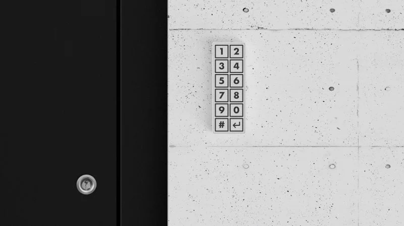
touch_matrix_Y24.zip for black labels on a white PCB and touch_matrix_Y23.zip for white labels on a black PCB. 1 It also has case_mid_final.stl for the enclosure, main.cpp for touch handling, Zigbee reporting, and power management, plus keypad_automation.yaml for Home Assistant actions. 1The interface is simple enough to trust near a door. The front panel is a 2x6 grid with digits 1-9, 0, Clear, and Enter; the labels are printed directly into the PCB solder mask, so there is no membrane overlay or glued label to wear off. 1 The touch matrix uses the MPR121 controller, and the ESP32-C6 handles the wireless side through Zigbee, with Matter or Thread described as possible alternatives on the same chip. 2
Battery life is the other reason this beat flashier projects this week. The build uses a 1300 mAh lithium-polymer cell, and both Hackaday and the repository describe roughly six months between charges under typical use. 2 The firmware sleeps after 10 seconds without a touch, puts the MPR121 into its slowest scan rate, and wakes the ESP32-C6 when the MPR121 interrupt line goes low. 1
Bill of materials
The estimated total is $23-30, assuming a small custom PCB order, commodity modules, and a 3D-printed case. 2 The project does not publish a distributor-priced line-item BOM, so treat the cost range as a planning estimate and check current pricing before ordering. 1
| Part | Spec / model | Qty | Estimated cost | Notes |
|---|---|---|---|---|
| ESP32-C6 dev board | ESP32-C6 DevKitC-1 class board with USB-C | 1 | ~$8 | Provides Zigbee-capable 802.15.4 radio and runs the firmware. 1 |
| Capacitive touch controller | MPR121 breakout or module | 1 | ~$3 | Reads the 12 capacitive key channels. 2 |
| LiPo battery | 1300 mAh lithium-polymer cell | 1 | ~$5 | Fills much of the internal volume and supports roughly six months between charges. 1 |
| Touch keypad PCB | Custom board from touch_matrix_Y24.zip or touch_matrix_Y23.zip | 1 order | ~$5 | Latest white-PCB revision and black-PCB variant are both supplied as Gerber ZIPs. 1 |
| 3D-printed case | case_mid_final.stl | 1 | ~$2 filament | Snap-fit shell with no visible screws. 1 |
| Small wiring and mounting materials | 5-pin wiring for MPR121, battery leads, white tack or similar wall mount | as needed | shop supplies | The repository shows a light assembly that can be mounted with small amounts of white tack. 1 |
The missing procurement detail is exact supplier part numbers. The repository names the main modules and publishes the Gerbers, but it does not give a verified Mouser, Digi-Key, or LCSC cart for the complete build. That is acceptable for an intermediate weekend project, but builders should confirm the ESP32-C6 board pinout and battery connector before soldering.
PCB and wiring overview
The custom PCB is both the touch surface and the visual faceplate. Buchstaller notes that the two supplied PCB color schemes use the same layout and touch pads; only the silkscreen color changes. 1 The rear side exposes a five-pin header for the MPR121: GND, INT, SCL, SDA, and 3.3 V. 1
The ESP32-C6 DevKitC-1 wiring is documented in the repository. I2C SDA goes to GPIO 18, I2C SCL goes to GPIO 4, the MPR121 interrupt line goes to GPIO 6, the battery ADC is read on GPIO 2, and the BOOT button on GPIO 9 is used for a Zigbee factory reset when held for more than three seconds. 1 The MPR121 channel map is also fixed: channels 0-8 are keys 1-9, channel 9 is 0, channel 10 is Clear, and channel 11 is Enter. 1
The mechanical stack is deliberately short: keypad face, electronics bay, and back cover. 1 The ESP32-C6 board sits at the bottom with USB-C available for flashing and charging, while the battery occupies most of the internal volume. 1 The case clips together without screws, which matches the design goal but puts more pressure on print tolerances than a screw-fastened enclosure would.
Firmware and Home Assistant setup
The firmware builds with PlatformIO, and the repository gives the upload command as
pio run --target upload. 1 The build targets Zigbee end-device mode with ZIGBEE_MODE_ED and uses partitions_zigbee.csv to reserve flash for Zigbee network storage. 1 The main library dependency called out in the README is Adafruit's MPR121 library. 1On first boot, the keypad scans for a Zigbee coordinator and joins through Home Assistant ZHA or Zigbee2MQTT. 1 In Home Assistant, the device appears as manufacturer
DrDoms and model KeyPad2. 1 It exposes two Zigbee endpoints: endpoint 1 reports the entered passcode and battery voltage through Analog Input plus Battery, while endpoint 2 reports battery state of charge as a percentage. 1The passcode behavior has one gotcha that should be handled before using the sample automation. The firmware prepends a leading
1 to every code so that leading zeros are not lost when the passcode is reported as a numeric value. 1 The README's example says a Home Assistant value of 12345 corresponds to typing 2-3-4-5, while a typed code of 0-1 appears as 101. 1 Copy the actual entity names from your Home Assistant device page, then test each code in Developer Tools before connecting it to a lock, cover, or door action.Reproduction difficulty
Rating: Intermediate. This is not a hard electronics project, but it is more involved than wiring together a breadboard sensor. You need to order a custom PCB, print the case, wire the MPR121 to the ESP32-C6, flash PlatformIO firmware, pair a Zigbee end device, and adapt a Home Assistant automation. The repository has 31 commits and 28 stars, which is enough activity to suggest a maintained hobby project, but it is not the same as multiple independent build logs. 1
The work splits cleanly:
- Order the PCB. Upload either
touch_matrix_Y24.ziportouch_matrix_Y23.zipto a board house and pick the color scheme that fits the mounting location. 1 - Print the case. Print
case_mid_final.stland test the snap fit before installing electronics. 1 - Wire the electronics. Connect the MPR121 header to the ESP32-C6 pins listed above, connect the LiPo to the ESP32-C6 battery pins, and route 3.3 V and ground to the touch PCB. 1
- Flash and pair. Upload with PlatformIO, open the serial monitor at 115200 baud, then add the device through ZHA or Zigbee2MQTT. 1
- Validate automations. Use the sample
keypad_automation.yaml, but replace the entity IDs and account for the leading-1 passcode behavior before any real door or cover action runs. 1
Special tools are modest: soldering iron, fine wire, 3D printer, USB-C cable, and a Zigbee coordinator already connected to Home Assistant. If your ESP32-C6 board and MPR121 breakout do not share the same connector style shown in the author's build, the project becomes a hand-wiring job rather than a pure plug-and-play assembly.
Go/no-go verdict
Build it if you already run Home Assistant with ZHA or Zigbee2MQTT and want a physical keypad without another cloud account. The project is especially attractive for a garage, workshop, front-door-adjacent automation, or any place where a phone app is the wrong interface.
Skip it for now if you need a weatherproof outdoor keypad, a certified access-control device, or a finished security product. The repo proves the hardware and automation path, but it is still a DIY smart-home node. Treat it as an input device for your own automation rules, test the passcode handling carefully, and do not make it the only control path for critical entry.
Cover image: image from A Custom Zigbee Touch Keypad — Hackaday
이 콘텐츠를 둘러싼 관점이나 맥락을 계속 보강해 보세요.