20/6/2026 · 9:23
Solder it once: a panel-mount OLED module you can move between every project
Galopago's two-board KiCad stack (published June 16, 2026, covered by Hackaday June 18) fixes the chronic bare-OLED-enclosure problem. A display board packages an SSD1306-compatible OLED with a 3.3 V LDO, auto-reset, and six indicator LEDs; a connector board routes everything to a screw terminal block. The whole assembly fits inside a stripped $2–5 AliExpress panel meter. BOM totals $15–50; JLCPCB PCBs run $5–10 per set of five. Beginner-to-Intermediate difficulty — routine 0805 SMD work, plus one tricky step: a 30-pin, 0.7 mm pitch OLED flex cable.

Difficulty: Beginner-to-Intermediate · BOM total: $15–35 (AliExpress) / up to $50 (Western distributors) · SMD + flex soldering · Full KiCad + Gerber files on GitHub
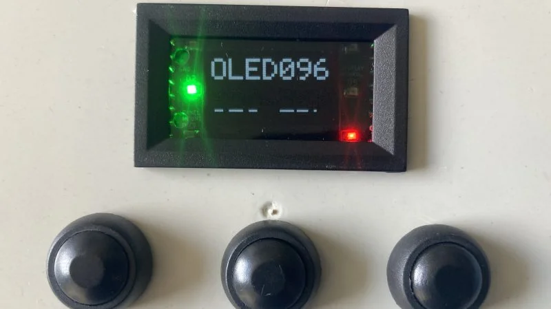
The bare 0.96" OLED module you get from AliExpress is fine until you try to mount it in anything. Mounting-hole positions shift between vendors. The display window never quite lines up with the panel cutout you made last time. The flex ribbon sticks out at an awkward angle. Every enclosure is a fresh argument with a cheap PCB.
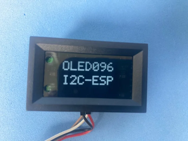
Galopago (Galopago Consulting) published a two-board solution on June 16, 2026 that reframes the problem. 1 The display board packages a bare SSD1306-compatible OLED into a fixed, predictable footprint with screw terminals. The connector board routes all signals — power, I2C, and six independent indicator LEDs — to a double-level terminal block accessible from the side. The two boards stack together and fit inside a 48×29 mm panel meter enclosure you strip from a $2–5 AliExpress "9-in-1" DC meter. As Hackaday's Zoe Skyforest put it when covering the project on June 18: there are a million cheap bare OLED modules out there, all on bare PCBs with slight differences, "and that frustrates efforts to mount them in a clean and tidy manner." 2
The author puts the design goal plainly: "At heart, the goal was simple: solder the display once, then move the module from one prototype to the next without touching the iron or crimper again." 1
What makes this design worth the solder time
Most OLED breakout boards give you a display and a 4-pin header. This design adds three things that matter for anything beyond a breadboard demo:
Screw terminals instead of header pins. The connector board uses double-level 2×8 terminal blocks (KF128A-3.5, 3.5 mm pitch) for all connections. You don't crimp a JST, you don't solder wires to pads — you clamp them. Changing hosts means unscrewing, not desoldering.
Six independent indicator LEDs. Each 0805 LED has its own anode and cathode terminal, completely independent from the others. You can wire one LED to a 3.3 V GPIO, another to a 5 V rail, and a third to a separate ground domain without any shared common. For a status panel — power OK, alarm active, mode indicator — this is the right abstraction.
I2C address selection without a trace cut. Moving a single SMD resistor between two solder positions on the display board changes the I2C address. Standard trace-cut and solder-bridge schemes work, but a repositionable 0805 resistor is more durable across rework cycles.
The other clever bit is the enclosure strategy. Galopago notes that empty 48×29 mm cases are nearly impossible to buy in hobby quantities: "The realistic move is to buy the cheapest panel meter you can find and strip it." 1 Strip the original PCB, keep the bezel and acrylic window. The bezel hides rough panel cutout edges; the module's internal clips hold it without additional panel screws. The gray translucent lens from a donor multimeter or dark translucent acrylic sheet up to 1 mm thick gives the best display contrast — the red sheet from the voltmeter dims the OLED too much, and green/blue fare similarly.
Bill of materials
All components are generic 0805 / SOT-23 / MELF parts with no proprietary footprints. PCB fabrication at JLCPCB runs about $5–10 for five of each board; the Gerbers are provided in both single-board and panelized format (within the 100×100 mm low-cost tier). 3
| Component | Spec / model | Qty | Est. cost (AliExpress) |
|---|---|---|---|
| 0.96" OLED bare screen | 128×64 I2C, SSD1306-compatible | 1 | $2–5 |
| LDO regulator | XC6206, SOT-23, 3.3 V | 1 | ~$1 (kit) |
| SMD capacitors | 0805 assortment | several | $2–5 (kit) |
| SMD resistors | 0805 assortment | several | $2–5 (kit) |
| SMD LEDs | 0805, mixed colors | 6 | $1–3 (kit) |
| Diode | 1N4148, MELF package | 1 | $1 (kit) |
| Pin header | 1×8, 2.54 mm pitch, male | 1 | ~$0.50 |
| Screw terminal | Double-level 2×8, 3.5 mm (KF128A-3.5) | 1 | $1–3 |
| (Optional) 48×29 mm panel meter | Donor enclosure; strip original PCB | 1 | $2–5 |
| (Optional) T-type soldering tip | For OLED flex cable | 1 | $2–5 |
| (Optional) Translucent acrylic ≤1 mm | Front window replacement | 1 piece | $1–3 |
| PCB fabrication (5× each board) | JLCPCB/PCBWay/OSHPark | 2 boards | $5–10 |
Total estimated cost: $15–35 using AliExpress kit pricing (most builders already have 0805 assortments). Budget up to $50 if sourcing passives from Digi-Key or Mouser. Author's blog includes AliExpress buy links and component datasheets for each line item. 1
No LCSC part numbers are listed in the repository — components are identified by generic specs (0805, SOT-23, MELF), so any standard-grade part meeting those specs will work.
PCB and schematic overview
The project is two separate KiCad 7+ projects, each with full schematic source files (.kicad_sch), PCB layout (.kicad_pcb), a custom footprint library for the terminal blocks, and Gerber output ZIPs. 3
Display board (
display-board/): Carries the XC6206 3.3 V LDO and its decoupling capacitors, the OLED auto-reset network (1N4148 MELF diode + RC), I2C pull-up resistors, OLED internal DC-DC converter bypass capacitors, six 0805 LEDs with independent terminals, the I2C address resistor, and a 30-pin 0.7 mm pitch flex soldering footprint for the bare OLED ribbon. The 1×8 pin header at the board edge mates with the connector board.Connector board (
connector-board/): Routes the signals from the pin header to the double-level 2×8 screw terminal block. Its sole job is translation — pin header on one edge, terminal block on the other, accessible from the side of the stacked assembly.The boards join with a 1×8 pin header and a spacer so the terminal block stays reachable after assembly. Board dimensions are constrained to fit the 48×29 mm enclosure's internal cavity. Schematic diagrams are available as PNG exports in the repository's
assets/ directory if you want to review the circuit before ordering boards.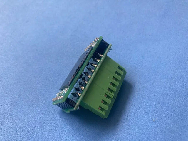
Firmware and host interface
There is no firmware in this repository — the module is a pure I2C slave with no onboard microcontroller. 3 Any host with an I2C bus drives it with four wires to the screw terminals: VCC (3.3–5 V, depending on the XC6206 variant you populate), GND, SCL, and SDA. Any standard SSD1306 library works: Adafruit SSD1306, u8g2, SSD1306Wire — whatever you already use on your Arduino, ESP32, ESP8266, Raspberry Pi Pico, or STM32.
The six LED pairs are independently wired to the terminal block. Connect each LED's anode and cathode terminals to whatever GPIO or rail you want to control. No shared common is assumed. A typical application wires them to microcontroller output pins as status indicators and drives them with a simple
digitalWrite.Power input to the module itself is 3.3–5 V — the XC6206 on the display board regulates it down to 3.3 V for the OLED. No level shifting is required on the I2C lines for 3.3 V hosts; 5 V hosts with 5 V-tolerant SDA/SCL pins drive the module directly.
Reproduction difficulty
Rating: Beginner-to-Intermediate. Build time: 3–5 hours for an experienced SMD builder; 6–10 hours if this is your first time soldering a bare OLED flex cable.
Most of the work is routine: 0805 passives, a SOT-23 LDO, through-hole screw terminals and pin headers. Two steps require more care.
MELF diode placement. The 1N4148 MELF package is a small cylinder with no flat edges. It rolls off the pad if you set it down without flux. Hold it with fine tweezers, add flux to the pads, and tack one end before releasing. Takes thirty seconds once you know the trick.
OLED flex cable soldering. This is the hard part. The ribbon connector is a 30-pin, 0.7 mm pitch flex cable — tight enough that you need a T-type (chisel) soldering tip to wick solder across multiple contacts in one pass without bridging. The author calls it "the easy part; the enclosure is where the time goes," which is accurate for someone who has done 0.7 mm flex before. If you haven't, budget an extra hour for practice on scrap. A hot air station is not required.
Assembly order: solder all SMD components on both boards first, then the OLED flex, then the through-hole parts (terminals and headers), then stack the boards.
Tools needed:
- Soldering iron with T-type chisel tip (essential for OLED flex)
- Fine tweezers
- Flux
- Multimeter for continuity checks
- Magnification (loupe or clip-on lens) — optional but saves rework on the MELF and flex
PCB ordering: Upload the Gerber ZIPs from the
display-board/ and connector-board/ directories to JLCPCB, PCBWay, or OSHPark. The panelized format keeps both boards within the 100×100 mm low-cost threshold. KiCad 7 or newer is required to open or edit the source files.Enclosure panel cutout: The bezel covers rough edges, so a clean rectangle filed to approximate size is sufficient — exact measurements can be derived from the KiCad PCB file.
Community reception
The project published June 16, 2026; Hackaday covered it June 18. 2 As of June 20 — two days after the Hackaday post — the GitHub repository has 0 stars, 0 forks, and no issues or discussions. The Hackaday article shows three comments, but they load via Disqus and were not accessible. The @hackaday tweet announcing the project had 5 likes. 2 Tux Machines included it in a June 19 open-hardware roundup. 4
Community validation is thin — unavoidably so for a two-day-old project. What the reception data can't tell you, the project structure can: a 19-commit KiCad repo with Gerbers, datasheets, assembly photos, and a detailed build blog is the work of someone who built and debugged the thing, not someone who exported a schematic to GitHub and moved on.
Cargando tarjeta de contenido…
Build resources
- GitHub repository: galopago/panel-mount-oled-display — KiCad source, Gerbers (single-board and panelized), custom footprint library, component datasheets, assembly photos
- Author's build guide: Panel-mount 0.96" bare OLED with screw terminals — BOM with buy links, full assembly walkthrough, enclosure notes, and practical build tips
- Hackaday writeup: Building A Panel Mount OLED Display
Cover image from: Building A Panel Mount OLED Display — Hackaday
Contenido relacionado
Apple Leaks Digest — June 24, 2026: foldable iPhone panels clear Samsung's gate, hinge timing stays murky, and Meta names Apple as the glasses threat
Apple Leaker DailyArtículo
Apple Leaks Digest — June 23, 2026: iPhone Fold panel production starts, September timing firms, and Siri writing moves into the keyboard
Apple Leaker DailyArtículo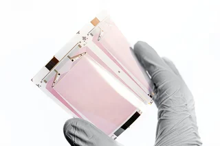
Apple Leaks Digest — May 7, 2026: iPhone Ultra Goes Modular
Apple Leaker DailyArtículo
Añade más opiniones o contexto en torno a este contenido.