1915 Çanakkale Bridge: Engineering the world's longest suspension span
The 1915 Çanakkale Bridge (opened March 18, 2022) broke Akashi Kaikyō's 24-year world record with a 2,023 m main span — achieved through 1,960 MPa PPWS cable wire, a 3.5 m aerodynamic twin-box deck, and 334 m towers 51 m taller than Akashi's. This case study traces every forced decision: gravel-bed seismic isolation 15 km from the North Anatolian Fault, a pile-count error caught by Arup's independent verification, dry-dock caisson prefabrication with 36-hour precision submergence, and completion 18 months ahead of schedule. A 2026 SBAS-InSAR study and the world's largest suspension-bridge SHM system (1,000 sensors) provide the first post-opening structural validation.

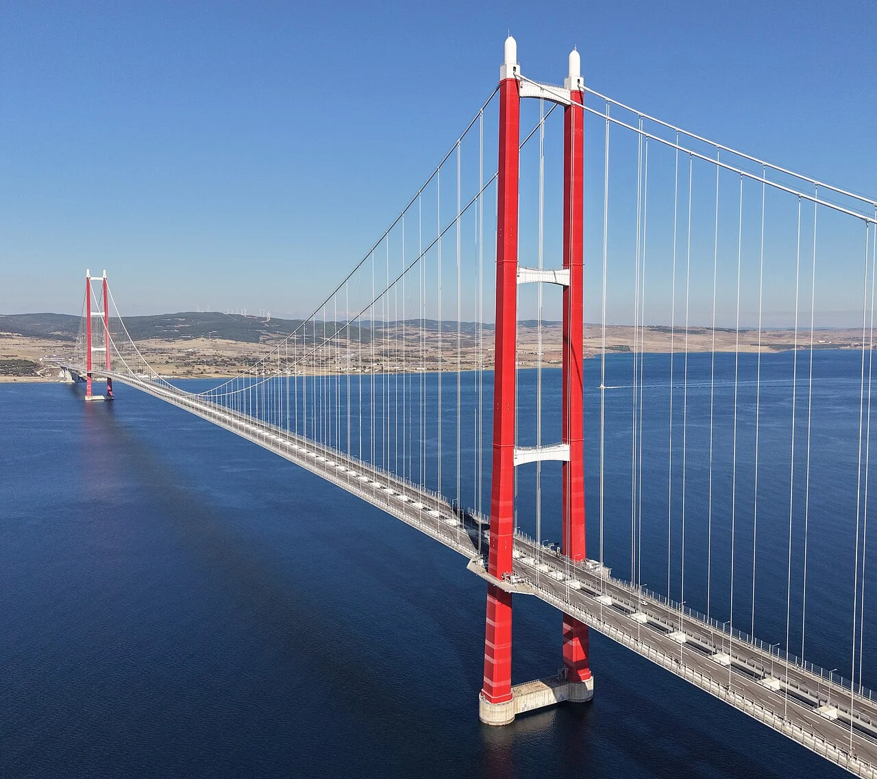
On March 18, 2022, Turkish President Recep Tayyip Erdoğan crossed the Dardanelles Strait by car over a bridge that had not existed four years earlier. The date was deliberate: March 18 is Çanakkale Victory Day, commemorating the 1915 Ottoman naval repulse of the Allied fleet during the Gallipoli campaign. The bridge opened 18 months ahead of schedule, in the centennial year of the Turkish Republic — whose founding in 1923 is encoded directly into its main span of 2,023 metres, the longest in the world. 1
The bridge's name carries four interlocking numerical symbols. "1915" is the Gallipoli year. The 2,023 m span references 1923, the Republic's centennial. The cable intersection point (IP) sits at exactly 318 m above sea level — 3/18, March 18. And the total tower height of 334 m includes the ornamental corbels that bring the crown to that symbolic figure. 2 As COWI Project Director Inger Birgitte Kroon noted, the symbolic numbers also produced structurally sound geometry: "The 318-metre-high towers and span of 2,023m along with reasonable navigation clearance generate a sag-to-span ratio very close to 1:9 — likely optimal for such a bridge. It's not that we had to suffer to achieve this." 2
The bridge is a tangible product of a Turkish-South Korean-Danish alliance: designed by COWI A/S (Denmark) as lead detailed designer, with PEC (South Korea) handling cable and approach bridge design, and with independent design verification by Arup Group (UK) and Aas-Jakobsen (Norway). Construction was carried out by the DLSY joint venture — Daelim (now DL E&C, South Korea), Limak Holding (Turkey), SK Ecoplant (South Korea), and Yapı Merkezi (Turkey). It is a peculiar irony that the nations once at war on those same shores — Australia, Britain, France, New Zealand — were later represented in the international design and construction teams. 3
The Çanakkale Bridge broke Akashi Kaikyō's 24-year hold on the world record by 32 m, stretching from 1,991 m to 2,023 m. What follows is an account of exactly how that was done — and what it means for the engineering of long-span bridges.
Why here, and why so long?
The Dardanelles Strait — 61 km long, between 1.2 and 6 km wide — has never had a fixed crossing. Since antiquity, armies, merchants, and migrants have relied on ferries. The ferry crossing at the bridge site takes up to five hours in heavy traffic; the bridge reduces it to six minutes. 4 That time saving alone has an economic value; President Erdoğan cited projected annual savings of €415 million in fuel consumption and carbon emissions alone, and the project's own analysis forecast a US$5.7 billion addition to Turkey's GDP over the concession period. 1
The bridge is the centrepiece of the 324 km Kınalı-Tekirdağ-Çanakkale-Savastepe Motorway (O-6), part of Turkey's role in the Middle Corridor trade route — the land link from China's Belt and Road Initiative through Central Asia and Turkey to Europe. 1 That geopolitical context, not just domestic traffic demand, explains the scale of public investment.
The span length was not chosen for vanity. The Dardanelles at the crossing point is approximately 2 km wide at water level, and the 70 m navigational clearance required by Turkish and international maritime authorities — the strait handles more than 40,000 vessels per year, including very large crude carriers — forced the towers to the shore. 2 Once tower positions were fixed by shore topography and shipping lane requirements, a 2,023 m span was the geometry that resulted. The symbolic number — matching 1923 — required bringing the schedule forward by one year (from a planned 2023 opening to 2022), but the span itself was essentially dictated by the crossing.
The project was not the first attempt to bridge the Dardanelles. An earlier concept was developed in 1989, proposed again in 1994, and formally shelved in 1995 specifically because seismic risk near the North Anatolian Fault was considered unresolvable with available technology. 5 The project was revived only after 2010, once performance-based seismic engineering had matured sufficiently to handle the site conditions. That 15-year wait is itself a data point about the seriousness of the geotechnical challenge.
The total project cost was €2.5 billion (roughly US$2.7–2.8 billion), funded through a public-private partnership with a 16-year concession period. Financial close was reached with 25 financial institutions from 10 countries — 70% international banks, 30% Turkish — in approximately one year. CFO Murat Sarikaya called it "kind of a miracle." 5 Toll at opening was ₺200 (roughly €6.78); by 2024 it had been raised to ₺1,260, reflecting Turkish inflation rather than traffic shortfall.
The span equation: cable, deck, and towers working together
Suspension bridges have a well-defined performance envelope. The maximum economical span is governed by two competing factors: the dead weight of the deck per metre (which is supported by the cables) and the tensile capacity of the cable wire. The longer the span, the higher the fraction of cable capacity consumed just holding up the structure — leaving less available for live load. Akashi Kaikyō stretched this envelope to 1,991 m in 1998 using the strongest wire available at the time (1,770 MPa) and a stiffening-truss deck 14 m deep. Çanakkale extended it by attacking both sides simultaneously. 1 6
The following table summarises the key structural comparison:
| Dimension | 1915 Çanakkale | Akashi Kaikyō |
|---|---|---|
| Main span | 2,023 m | 1,991 m |
| Total bridge length | 4,608 m | 3,911 m |
| Tower height (to cable IP) | 318 m | 282.8 m |
| Total tower height | 334 m | 282.8 m |
| Deck depth | 3.5 m (twin-box) | 14 m (stiffening truss) |
| Deck width | 45.06 m | 35.5 m |
| Vertical clearance | 70 m | 65 m |
| Cable wire strength | 1,960 MPa | 1,770 MPa |
| Cable wire diameter | 5.75 mm | 5.23 mm |
| Deck type | Aerodynamic twin-box | Rigid stiffening truss |
| Construction duration | ~5 years | 10 years |
Factor 1: Higher-strength cable wire. The main cables use a Prefabricated Parallel Wire Strand (PPWS) system with wire at 1,960 MPa minimum tensile strength — 11% stronger than Akashi's 1,770 MPa. Each wire is 5.75 mm in diameter (vs. Akashi's 5.23 mm). The strands are arranged in hexagonal bundles of 127 wires; the main span carries 144 strands per cable, and the side spans carry 148 strands. 5 7 An 11% improvement in wire strength translates directly into either a longer achievable span, a smaller cable diameter, or a higher safety factor — the design team applied it toward span extension.
Factor 2: The aerodynamic twin-box deck. Akashi's stiffening-truss deck is 14 m deep and acts as a rigid beam that keeps the deck from deforming under wind and live load. Çanakkale uses a twin-box girder — two stiffened closed steel box sections separated by a 9 m central air gap, transversely connected by 3 m-wide cross-girders spaced 24 m apart. The structural depth is just 3.5 m. 5 As Yapı Merkezi co-founder Ersin Arıoğlu summarised: "Akashi Kaikyō's deck is rigid, while this one is aerodynamic." 5 A thinner, lighter deck means less dead load per metre — fewer tonnes of steel that the cables must support before the first vehicle crosses.
Factor 3: Taller towers. At 334 m total height with the cable IP at 318 m, the towers are 51 m taller than Akashi's 282.8 m. In suspension bridge geometry, taller towers produce a larger sag in the cable relative to the span, which reduces the horizontal component of cable tension. Lower horizontal tension allows the same cable area to span further without exceeding allowable stress. 1 The sag-to-span ratio of approximately 1:9 is close to the theoretical optimum for this scale. The symbolic 318 m IP height happened to land almost exactly on that optimum — which is why COWI's Kroon noted there was no engineering sacrifice to accommodate it.
The total wire length across both cables is over 162,000 km — sufficient to loop around the Earth four times. 7 There are 314 hanger ropes made of parallel wire strand (PWS), with diameters ranging from 110 to 175 mm, installed at 24 m intervals. Bearings and bushings were added to hanger connections to minimise secondary stresses from deck deflections. 7
The foundation problem: caissons, piles, and seismic isolation
Suspension bridge towers must be founded where the topography requires them, not where the geology invites them. The Dardanelles shoreline at the Lapseki-Gelibolu crossing sits above Holocene clay (European side) and Pleistocene clay and sand (Asian side), with Miocene mudstone beneath both. Neither site is ideal for a structure that will impose enormous compressive and lateral forces. And the bridge sits approximately 15 km from the North Anatolian Fault Zone — a 1,500 km right-lateral strike-slip fault capable of Mw 7.6 events, to which 90% of Turkey is exposed in some form. 8
The design response was to treat each tower foundation as an isolator rather than a fixed anchor.
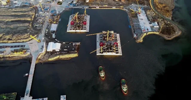
Caisson construction. Each tower foundation is a reinforced concrete cellular caisson measuring 74.0 m × 83.3 m in plan and 16 m high, cast in C45/55 concrete with B500 reinforcement steel. Floating weight was up to 54,800 tonnes. 5 The caissons were built in a purpose-built dry dock on the European side — an 16,000 m² facility with 1,328 pilings — then floated to a wet dock for continued concrete work, and finally floated out to their final positions and submerged. Each submergence operation took approximately 36 hours and required 152,000 m² of water ballast, with hydraulic jacks providing final alignment within a 200 mm tolerance. 7
Pile reinforcement. The seabed beneath each caisson was reinforced with steel pipe piles 2,500 mm in diameter, 20–25 mm wall thickness, driven to depths of 20–46 m. According to ENR, approximately 368 piles were used in total; a separate technical summary by engineer Beomsoo Park gives 192 piles on the European side and 165 on the Asian side (totalling 357). The ~11-pile discrepancy has not been officially reconciled; both figures appear to derive from project data. 5 7 The piles reduced European tower settlement by approximately 80% and significantly increased lateral resistance against both ship impact and seismic forces.
The gravel-bed isolation system. On top of the piles, the team placed a 3 m-thick gravel layer covering the tower footprint. The caisson base sits on this gravel. Under typical operating conditions, the gravel acts as a stable platform. Under extreme horizontal loads — a design earthquake or a ship impact well beyond the code requirement — the caisson can dissipate energy by sliding on the gravel bed without transferring damaging forces to the tower shaft or superstructure. COWI's Kroon described the logic: "The prime idea of the gravel bed with steel pipes was to strengthen the structure and soil to withstand ship impacts and earthquakes — working with huge horizontal forces. In principle, at a very high horizontal load, the tower could dissipate energy by moving on the gravel bed without damaging the structure." She also noted: "We have not found any situations where it will actually move, and hence, it is an extra safety measure." 2
Seismic performance levels. The design was based on Probabilistic Seismic Hazard Analysis (PSHA) and a Performance-Based Seismic Design (PBSD) approach with three target performance levels: Frequent Earthquake Event (145-year return), Safety Evaluation Earthquake (975-year return), and No-Collapse Earthquake (2,475-year return, corresponding to 4% probability of exceedance in 100 years). Nonlinear time-history analysis was used throughout, with the gravel-bed fuse activated only at the NCE level. 9 Steel towers were chosen over concrete specifically to reduce seismic inertia — steel weighs less, so the same earthquake ground motion generates lower inertial forces. 2
Ship impact. More than 40,000 vessels transit the strait annually, including tankers up to 265,000 DWT. The design impact criterion was set at an annual probability of 10⁻⁴ (once in 10,000 years), corresponding to a 370 MN design impact load — assessed against a 260,000 DWT bulk carrier at 11.9 knots and a 180,000 DWT container vessel at 14.3 knots. 9 The navigational clearance of 70 m width and 1,600 m depth is stated to be the largest of any comparable suspension bridge globally. 9
An independent check that found a real error. Arup's independent design verification uncovered errors in the rebar design of the caisson walls. Using Oasys GSA with 2D shell elements, Arup's RC Slab Design postprocessor flagged concrete failures in specific wall areas. Drawing Mohr circles of the failing elements, engineers determined the failure mode was in-plane shear — and critically, no amount of orthogonal (horizontal + vertical) reinforcement could prevent it, because the principal stresses were diagonal. The three available solutions were: increase concrete grade, increase wall thickness, or align reinforcement with the principal stress directions. The team chose the third option: local addition of diagonal rebar in affected wall panels. 10 This is a useful reminder that independent verification of caisson reinforcement on mega-scale foundations is not ceremonial.
Wind and aerodynamics: why the gap matters
The Dardanelles is not a benign wind environment. The strait acts as a channelling corridor for the regional flow, with the design wind speed set at Vb = 29.0 m/s (100-year return period, with a 10% allowance for model uncertainty). 9 At a span-to-depth ratio of 1:578, the Çanakkale deck is the most slender suspension bridge deck relative to span ever built. Slender decks that are not aerodynamically shaped can flutter — an aeroelastic instability that destroyed the original Tacoma Narrows Bridge in 1940 and has constrained suspension bridge design ever since.
Akashi Kaikyō's solution was a stiffening truss: make the deck so rigid it cannot deform in the mode that triggers flutter. The penalty is 14 m of structural depth and corresponding dead weight. Çanakkale took the opposite approach — make the deck aerodynamically neutral so that wind forces do not couple into a flutter mode in the first place.
The twin-box geometry. The deck consists of two closed steel box girders, each part of the 45 m overall width, separated by a 9 m central air gap. The gap is not wasted space: COWI tested gap widths of 7 m, 8 m, and 9 m in combination with chamfer angles of 0°, 30°, and 60°, and wind barrier heights of 3 m and 4 m. The 9 m gap with appropriate chamfering and 4 m wind barriers (50% porosity) maximised the flutter onset wind speed. 9 COWI's Andersen explained the mechanism: "The gap between the two box girders ensures the aerodynamic stability of the deck in very strong wind." 2
Wind tunnel testing. Two independent wind tunnel campaigns validated the deck geometry. Sectional model tests were performed at Western Ontario University's Boundary Layer Wind Tunnel Laboratory (BLWTL) in Canada in 2017 and at Southwest Jiaotong University's Research Centre for Wind Engineering (RCWE) in China in 2018. Full-bridge aerodynamic model tests followed. 9 The results confirmed: design flutter wind speed 68.4 m/s; tested flutter onset 77 m/s full scale; no flutter instability observed up to 83 m/s full scale. 9 The operating wind speed of 29 m/s sits well below any of these thresholds.
Post-opening academic validation. In 2024, a team from the Technical University of Denmark (DTU) — Maja Rønne, Allan Larsen, Jens H. Walther, and Søren V. Larsen — published a wind tunnel study on twin-box decks using section geometry closely based on the Çanakkale cross-section, presented at the 16th International Conference on Wind Engineering (ICWE16, Florence). Their finding: critical flutter wind speed increases with increasing positive static angles of attack (nose-up), due to a decrease in aerodynamic stiffness loss. The practical recommendation is that twin-box decks should be designed to have a positive moment coefficient at zero angle of attack and a positive, decreasing moment slope for increasing nose-up angles — a set of criteria the Çanakkale deck satisfies by its as-built geometry. 11
The deck also carries MAURER MSM® Swivel Joist Expansion Joints at each end, rated for ±1,400 mm movement (2,800 mm total travel). These are among the largest modular expansion joints ever manufactured, required by the thermal and seismic displacement envelope of a 2,023 m span. 5
Building it in under five years: construction innovations
The project launched in March 2017 and was contractually due for completion in September 2023. The bridge opened on March 18, 2022 — 18 months early. That schedule compression was not the result of corner-cutting. It was built into the construction strategy from the outset, driven by the political symbolism of the 2022 opening date. COWI's Kroon stated directly: "The pre-fabrication requirement was primarily coming out of a request for fast construction time. We've had a very tight construction schedule for this bridge." 2
Caissons built away from the site. Rather than constructing the tower foundations in situ — which would have required working in active shipping lanes — the caissons were cast in a purpose-built dry dock approximately 5 km from the tower sites on the European side. After the main structure was complete, the dry dock was flooded to float the caissons to a wet dock for continued work, then floated to their final positions and submerged. Each immersion required a year of data collection on currents, water temperature, depth, and salinity to model the operation. Final positioning was achieved within a 200 mm tolerance using hydraulic jacks. 5
Towers assembled in 32 segments per tower. Each 334 m steel tower was fabricated as 32 segments. The lower six segments — too heavy for a tower crane — were lifted by 300-tonne floating cranes. Australian contractor Marr Contracting supplied two M2480D HLL (Heavy Lift Luffing) cranes, each weighing 600 tonnes; they were transported 1 km and installed as complete units by a larger floating crane in a single day in November 2019. The upper 26 segments were then erected by tower cranes mounted on the caissons. 5 The critical innovation was sequencing: each new block was bolted first, allowing the crane to move immediately to the next lift while welders completed the previous joint. This eliminated the wait-for-weld delays that constrain conventional steel tower construction. 2 The second tower was completed on May 16, 2020. The 155-tonne upper cross-beam was lifted to 318 m height in approximately 30 minutes by a Marr crane perched 328 m above the water. 5
Cables installed by PPWS. With both towers complete, catwalks were installed — 4,270 m of working platform, 4.5 m wide, supported by spiral ropes. Cable saddles were placed at tower tops (90 tonnes each) and at the side saddles (60 tonnes each) using tower and crawler cranes. The PPWS method pre-bundles wire into 127-wire hexagonal strands at the factory and ships them coiled on reels, which are then unreeled across the catwalk and anchored into the anchor blocks at each end. This approach is faster and more quality-controlled than traditional aerial spinning. 7 12
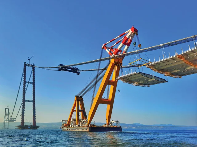
Deck installation from two directions simultaneously. The 153 deck segments — each 48 m long, 45 m wide, and weighing up to 850 tonnes — were prefabricated at four yards and transported to site by barge. Installation used the 5,000-tonne floating crane Asian Hercules III (Singapore-flagged, 106 m long) and four pairs of lifting gantry cranes. Up to four segments were placed per day in carefully planned windows when wind speeds were within tolerance. Segments were temporarily pinned with hinge joints to allow the deck to deform during installation, then field-welded at completion. The last of the 153 segments was placed on November 13, 2021. 5 7
Anchorage alignment optimisation. COWI shifted the bridge alignment slightly within the allowable corridor to place both gravity-type anchor blocks in substantially better soil conditions. The European anchorage measures 50.0 m × 74.0 m at the base, with 68,800 m³ of concrete and 6,400 tonnes of rebar, cast in 2 m-high layers. The Asian anchorage is larger at 56.0 m × 80.0 m, with 92,000 m³ of concrete and 10,832 tonnes of rebar. 5 7 By moving the anchorage locations, the team achieved major reductions in concrete quantities — a lower carbon footprint and a better schedule. As COWI's Andersen explained: "The early decisions you make are where you can really bring about the biggest optimisations." 2
Logistical complications. The project was not without friction. A COVID-19 lockdown in 2020 shut the site for approximately six months, but most major material purchases had been placed before the pandemic. 3 Pile driving was paused at least five times for dolphin passage, with three marine mammal observers stationed on site. More than 1,000 Pinna nobilis (noble pen shell) mussels — a protected species — were relocated before caisson submergence. The supply chain involved subcontractors from 22 nations, with cranes from Australia, wire from South Korea, design from Denmark and Norway, and financing from ten countries. 5
Key specifications
| Parameter | Value |
|---|---|
| Main span | 2,023 m |
| Side spans | 2 × 770 m |
| Total suspension length | 3,563 m |
| Total bridge length (with viaducts) | 4,608 m |
| Tower height (total) | 334 m |
| Cable intersection point height | 318 m above sea level |
| Deck height above water | 72.8 m |
| Navigational clearance | 70 m vertical, 1,600 m horizontal |
| Deck width | 45.06 m (6 traffic lanes) |
| Deck structural depth | 3.5 m |
| Span-to-depth ratio | 1:578 |
| Central gap (twin-box) | 9.0 m |
| Cable wire strength | 1,960 MPa |
| Cable wire diameter | 5.75 mm |
| Wires per strand | 127 |
| Strands per cable (main span) | 144 |
| Total wire length (both cables) | >162,000 km |
| Tower steel grade | S460M/ML |
| Tower steel weight (both towers) | ~36,300 tonnes |
| Caisson dimensions | 74.0 m × 83.3 m × 16 m |
| Pile diameter | 2,500 mm |
| Pile depth | 20–46 m |
| European anchorage concrete | 68,800 m³ |
| Asian anchorage concrete | 92,000 m³ |
| Expansion joint travel | ±1,400 mm (2,800 mm total) |
| Design wind speed | 29.0 m/s (100-year return) |
| Flutter onset wind speed (tested) | 77 m/s full scale |
| Seismic design return period | 2,475 years (NCE level) |
| Ship impact design load | 370 MN |
| Deck segments | 153 |
| Design service life | 100 years |
Note on pile count: ENR reports approximately 368 total piles; Beomsoo Park's technical summary gives 192 (European side) + 165 (Asian side) = 357. Both sources cite project data and the discrepancy has not been officially resolved. The likely explanation is a difference in reporting scope (whether certain secondary or raking piles are counted).
Monitoring and operational resilience
The 1915 Çanakkale Bridge has a structural health monitoring (SHM) system that Sixense (a Soletanche Freyssinet company) describes as the world's largest ever installed on a suspension bridge: more than 1,000 sensors across the entire structure. 13 The system monitors deck and cable vibrations, stress concentrations in mechanical elements, temperature at multiple points, weather data, seismic activity, and traffic load. A rainflow counting module specifically tracks cumulative stress cycles in the orthotropic slab to give advance warning of fatigue accumulation. 14 The system is not purely reactive: Sixense states that it "will allow scenario predictions — the operator will be able to estimate aging of the structure according to traffic increase predictions." 13
The seismic monitoring component was supplied by QuakeLogic: four LUNITEK downhole accelerometers (Tellus-BH-FB160) and two force-balance surface accelerometers (LTFB-160), connected to 24-bit ATLAS digitisers on each side, feeding QuakeLogic's SMARTBRIDGE SHM software in real time. 15
First satellite deformation study. In March 2026, researchers Duygu Arikan Ispir and Hasan Bilgehan Makineci of Konya Technical University published the first comprehensive satellite-based deformation analysis of the bridge since its opening, in Remote Sensing (MDPI). They applied the SBAS-InSAR technique to 146 Sentinel-1 synthetic aperture radar scenes covering February 2022 to January 2025. The main bridge spans showed no significant deformation. However, the study detected localised line-of-sight (LOS) displacement concentrated near the Lapseki approach on the Asian side, with a peak cumulative value of approximately −90 mm near the Asian anchorage (maximum LOS displacement across the full domain: −101 mm). 16
The authors interpreted the localised movement as likely geotechnical in origin — the Lapseki area has documented active landslide history since the late 19th century — rather than structural failure. They note explicitly that LOS-only measurements cannot definitively separate structural from geotechnical deformation drivers, and recommend targeted GNSS/levelling campaigns and ascending-descending InSAR fusion to resolve the question. Annual deformation rates across the three years of study remained within predicted engineering limits. 16 The bridge's seismic isolation foundation design — precisely the feature that allows controlled differential movement of the caisson on the gravel bed — means that moderate ground movement near the anchorage zone does not automatically translate to structural distress.
The first vessel collision. On June 11, 2025, the cargo vessel M/V New Life made contact with a bridge pier in the Çanakkale Strait. An academic analysis using the Ishikawa (fishbone) method — the first published ahead of the official investigation — identified three primary contributing factors: navigating without a pilot, probable crew fatigue, and non-compliance with COLREG (the International Regulations for Preventing Collisions at Sea). The analysis used a two-stage Delphi process with nine maritime experts, achieving a Kendall's W concordance coefficient of 0.829 (indicating strong statistical consensus). 17 The official accident investigation had not been published as of this writing. The incident illustrates the continuing tension between the strait's status as a major international shipping lane and the presence of bridge piers within it — the same tension that drove the 370 MN ship impact design load in the first place.
Legacy: what Çanakkale changed
The 1915 Çanakkale Bridge did not invent any of its key technologies. PPWS cables, twin-box aerodynamic decks, and performance-based seismic design all existed before 2017. What the project achieved was the simultaneous optimisation of all three to a level that extended the achievable suspension-bridge span from 1,991 m to 2,023 m, while completing construction in five years rather than the ten it took to build Akashi.
That simultaneous optimisation is the engineering legacy. The three enabling factors — stronger wire, lighter deck, taller towers — are not independent knobs. Changing one requires recalculating the others. The Çanakkale design team, led by COWI with DL E&C's construction team and Arup/Aas-Jakobsen's independent verification, demonstrated that these variables could be balanced at a new equilibrium point. In 2026, the first English-language peer-reviewed retrospective from the construction consortium appeared in Structural Engineering International (IABSE): Kim and Choi of DL E&C published "Realization of the Longest Suspension Bridge, 1915 Çanakkale Bridge" (SEI Vol. 36, Issue 2, pp. 214–218). 18 The full text is behind the Taylor & Francis paywall and was not available for this analysis, but the paper's existence marks the bridge's formal entry into the IABSE engineering record.
Several specific technical contributions stand out:
The twin-box deck as the dominant long-span paradigm. Akashi used a stiffening truss because 1990s aerodynamic knowledge required it. By 2017, twin-box aerodynamics had been validated on Great Belt East Bridge (1,624 m, 1998), Osman Gazi Bridge (1,550 m, 2016), and others. Çanakkale pushed the twin-box to a scale and slenderness — 1:578 — where it had not been tested before. The DTU flutter study published after the bridge opened confirmed the stability mechanisms and produced design recommendations (positive moment coefficient at zero angle of attack, decreasing moment slope with positive pitch) that will be referenced by designers of the next generation of spans, wherever those may be built. 11
Performance-based seismic isolation for long-span bridges in active fault zones. The combination of gravel-bed energy dissipation, performance-level-based design, and real-time seismic SHM is a template that directly addresses the problem that shelved earlier Dardanelles proposals in 1995. The approach decouples structural integrity from soil behaviour at extreme loads — a meaningful advance for any future crossing near active fault systems. A 2026 paper in Engineering Structures on fluid viscous damper seismic design for long-span suspension bridges uses the Çanakkale Bridge as a case study (Elsevier, DOI: 10.1016/j.engstr.2026.x); the full text was not publicly accessible at time of writing and is not cited here.
The SHM scale. A 1,000-sensor monitoring installation for a single bridge structure, with predictive modelling and real-time earthquake processing, sets a new operational baseline for how major crossings are managed. The integration of InSAR satellite monitoring with the on-structure sensor network — as the 2026 Remote Sensing paper begins to explore — points toward a hybrid monitoring methodology that does not require physical access to every component.
The construction-speed template. Completing a world-record suspension bridge in five years, including 18 months ahead of a tight contractual deadline, during a global pandemic, is itself a result worth studying. The enabling moves — dry-dock caisson prefabrication, bolt-first-weld-later tower erection, multi-crane-parallel deck installation — individually are not new, but their systematic combination and the management of a 22-nation supply chain at this scale will influence project-planning approaches for future mega-spans.
The question practitioners will ask next is: can the Çanakkale envelope be extended further? A 2,500 m span would require still stronger wire (beyond 1,960 MPa, approaching the limits of available galvanising chemistry), a deck potentially thinner than 3.5 m (requiring composites or novel steel forms), and towers approaching or exceeding 400 m. All of these are technically conceivable; none is currently off-the-shelf. What Çanakkale demonstrates is the methodology for how to ask that question: identify the binding constraint, find the most cost-effective way to relax it by the minimum necessary amount, and re-optimise the whole system. That systematic approach — not the specific numbers — is the real inheritance.
As Ersin Arıoğlu, co-founder of Yapı Merkezi, said when the bridge was taking shape: "Every new suspension bridge — it's like measuring the rate of civilization." 5 The 1915 Çanakkale Bridge moves that measure by 32 m and leaves engineers a clearer map of where the next 32 might come from.
Cover photo: 1915 Çanakkale Bridge, September 2025. Photo via Wikimedia Commons, CC BY-SA 4.0.
参考来源
- 1Wikipedia: 1915 Çanakkale Bridge
- 2STIRworld: COWI interview on the 1915 Çanakkale Bridge
- 3The B1M: Turkey Has Built the World's Longest Suspension Bridge
- 4The B1M: Why Turkey Built the World's Longest Suspension Bridge
- 5ENR: World's Longest Suspension Bridge Takes Shape in Turkey
- 6Wikipedia: Akashi Kaikyō Bridge
- 7LinkedIn: Beomsoo Park — 1915 Canakkale Bridge technical summary
- 8We Build Value: Great Bridges That Won Earthquakes
- 9IRF World Congress 2024 / Yapı Merkezi: Resilience Design of 1915 Çanakkale Bridge
- 10Oasys Software: How Arup used Oasys Structural software to verify the design of the 1915 Çanakkale Bridge
- 11arXiv: Flutter stability of twin-box bridge decks (Rønne et al., ICWE16)
- 12Structurae: 1915 Çanakkale Bridge
- 13Sixense Group: Monitoring of the structural health of the 1915 Çanakkale Bridge
- 14Taylor & Francis / CRC Press: Structural health monitoring of the 1915 Çanakkale Bridge in Turkey
- 15QuakeLogic: 1915 Canakkale Bridge Monitoring
- 16MDPI Remote Sensing: Determination of Slow Surface Movements Around the 1915 Çanakkale Bridge (2022–2024)
- 17Journal of Traffic and Transportation Research: M/V New Life Collision with the 1915 Çanakkale Bridge Pier
- 18Structural Engineering International: Realization of the Longest Suspension Bridge, 1915 Çanakkale Bridge
围绕这条内容继续补充观点或上下文。