Millau Viaduct — how one alignment decision built the world's tallest bridge pier

Millau Viaduct — how one alignment decision built the world's tallest bridge pier

In 1991, French highway planners locked in a plateau-to-plateau alignment for the A75 motorway that required a single 2,460-metre viaduct towering 270 metres above the Tarn gorge. This case study traces how that one decision cascaded into everything else: P2's 244.96 m pier shaft on shale, a steel deck substitution that cut weight from 120 t/m to 14.6 t/m, PERI climbing formwork advancing 4 m every three days, and a GPS-guided incremental launching system pushing 36,000 tonnes of steel 600 mm every four minutes — completing 37 days early with zero fatalities.
Engineering Marvel Teardown
2026/5/28 · 23:52
4 订阅 · 12 内容
The bridge exists because of a traffic jam. Every summer through the 1980s and 1990s, the Route Nationale N9 through the Tarn valley gorge turned the small town of Millau, in southern France, into a four-hour bottleneck on the Paris-to-Barcelona corridor. Tourists and lorries backed up for kilometres, funnelled through medieval streets because there was no other way across the 270-metre-deep Tarn gorge on the plateau-to-plateau crossing. 1
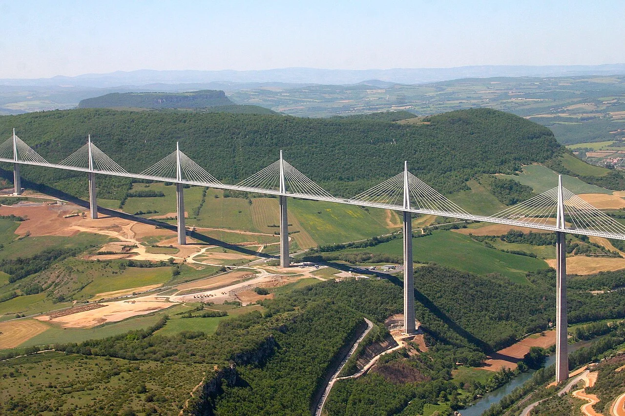
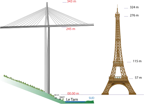
The engineering response, which opened on 16 December 2004, is a multi-span cable-stayed viaduct 2,460 metres long, carrying the A75 La Méridienne autoroute on a deck that floats up to 270 metres above the gorge floor. 1 Its tallest pier, P2, rises 244.96 metres from its foundation to its road deck, and the steel mast atop it adds another 88.92 metres — putting the mast tip at 343 metres above ground — taller than the Eiffel Tower's 330-metre tip. 1 2 For slightly over 21 years, from December 2004 until the opening of China's Changtai Yangtze River Bridge in September 2025, it held the title of the world's tallest bridge structure. 3
None of those numbers arose from a goal to set records. They arose from a single upstream choice: take the high line across the Tarn valley rather than the low one. What follows is an account of how that one alignment decision propagated into every structural, material, aerodynamic, and constructional challenge the team had to solve.

The bottleneck that required a sky-level solution

The A75 motorway project connected Clermont-Ferrand to Béziers, completing the Paris-to-Mediterranean spine through the Massif Central. The final segment crossed the Tarn gorge near Millau — and that crossing had no good options. French highway planners analysed four distinct route corridors through the 1980s, ranging from a far-eastern alignment requiring two bridges with 800–1,000 m spans, to a far-western route that was 12 km longer and required four separate viaducts. 1
The central Médiane corridor was selected, but it came in two sub-variants. The low option crossed the gorge at valley level — a 200 m river bridge plus 2,300 m of approach viaduct, plus a tunnel through the Larzac plateau on the south side. The high option crossed at plateau level — a single 2,500 m structure entirely above the gorge, 200 m or more above the river. The low option was eliminated by ministerial decree on 29 October 1991, for three compounding reasons: it intersected the local water table, it ran too close to the town of Millau and increased road noise exposure, and despite its apparently simpler geometry it was projected to cost more — because the tunnel and the lower valley bridge added complexity that offset the shorter pier heights. 1 2
Once the high option was confirmed, the dimensions of the problem became fixed: a single bridge roughly 2,500 m long, crossing terrain that dropped and then rose by more than 240 m beneath it, in a valley known for high sustained winds. From 1993 to 1996, the French government consulted seven architects and eight structural engineers individually, then commissioned five architect-engineer consortia to develop full concept proposals. An expert jury chaired by Christian Leyrit selected the entry by Michel Virlogeux (structural engineer, Sétra) and Norman Foster (Foster + Partners, architect) on 15 July 1996. 1 Their proposal was a seven-pier, eight-span cable-stayed structure with a slender steel-box deck — a design that, at the time of selection, had never been attempted at this combination of span length and pier height.

Structural concept — seven piers and a cable web

The most visually arresting fact about the Millau Viaduct is that its seven piers are not all the same height. The Tarn valley is not a flat-bottomed canyon: the north plateau sits higher than the south plateau, the valley floor itself undulates, and the road deck must maintain a continuous 3.025% longitudinal gradient throughout. The pier heights are therefore set by the geometry of the terrain beneath a rising deck, not by any uniform structural target. 1
PierHeight to road deck
P194.50 m
P2244.96 m
P3221.05 m
P4144.21 m
P5136.42 m
P6111.94 m
P777.56 m
Source: 2
P2 and P3 together form the world's two tallest bridge piers — they stand in the deepest part of the gorge, where the river valley floor is lowest and the deck must already be climbing toward the south plateau. P7, by contrast, is short because it sits on the rising south slope where the deck is already close to the ground.
The structural system is a multi-span cable-stayed viaduct. Eight spans — an end span of 204 m on each side, and six central spans of exactly 342 m — are suspended by 154 stay cables, each pier carrying 22 stays (11 cable pairs, one fan on each side of the pier). 1 The stays are arranged in a semi-fan geometry: all cables from a given mast anchor at the mast tip rather than being spread along the mast height (which would characterise a true harp arrangement), but they spread downward to deck anchor points at 12.51 m intervals along the deck. 2 This semi-fan layout concentrates horizontal thrust efficiently at the mast tip while distributing deck compression loads at manageable intervals.
The pylon shape above deck is an inverted Y — a single stem rising from the deck surface to 38 m above it, at which point the mast divides into two raking arms that anchor the cable fans on each side. Each mast is 88.92 m tall above the deck, weighs approximately 650–700 tonnes, and is made of S355/S460 steel. 2 The inverted-Y form was chosen over a conventional A-frame (which would have required a wide transverse base on the narrow deck) and over a single-mast design (which would have provided no inherent lateral stiffness in the plane of the deck). The Y-shape stiffens the mast against transverse wind loading while keeping its footprint within the 32-metre deck width.
Below the deck surface, each pier shaft tapers outward: the cross-section measures 16–17 m in the bridge's longitudinal direction and widens from 10 m at the top to 27 m at the base in the transverse direction. 2 Below approximately 90 m from the deck, each pier splits into two separate parallel hollow shafts — this bifurcation improves stability at the base while reducing the visual mass of the pier at mid-height. Each shaft is post-tensioned vertically with 19-strand tendons to manage the eccentric bending moments that stay cable tensions impose.

The wind problem and the airfoil deck

At 270 m above the valley floor, the Millau Viaduct deck sits permanently in the Tarn valley's prevailing wind field. Design wind speed is 225 km/h (140 mph). 1 The valley funnels and accelerates winds in a way that made aerodynamic behaviour the dominant structural design load — more consequential, in terms of shaping the deck cross-section, than the traffic live load the bridge carries.
The primary aerodynamic threat to a long-span deck is vortex-induced vibration (VIV). As wind flows past a bluff cross-section, it separates and forms alternating vortices on the lee side — the same phenomenon that causes wires to hum and chimneys to oscillate. For a bridge deck, if the vortex shedding frequency matches one of the deck's natural vibration frequencies, resonance can develop. Unchecked VIV produces oscillations that fatigue the structure and, in extreme cases (as at Tacoma Narrows in 1940), can lead to total failure. The concern at Millau was not catastrophic failure but deck oscillations large enough to affect safety and to generate unacceptable structural fatigue over the design life.
Greisch Ingénierie of Liège was responsible for the aerodynamic calculations and the pushing technique. Wind tunnel testing of deck section models led to a fundamental change in the cross-section geometry: the original deck profile was modified to an inverted aerofoil shape — a closed steel-box girder with the lower surface curved upward so that the cross-section generates negative aerodynamic lift (a downforce) in high winds, pressing the deck toward its supports rather than lifting it. 1 The deck edges were rounded to prevent flow separation that would initiate vortex shedding, and the bottom-flange geometry was optimised to ensure stable attached flow at the likely range of attack angles.
The deck is 4.20 m deep and 32.05 m wide. 2 Two separate carriageways of three lanes each sit within the box, with wind fairings on the outer edges — deflectors that redirect air flow around high-sided lorries and caravans to prevent crosswind overturning. The combination of box depth, inverted-aerofoil shape, and edge fairings produces a deck that is aerodynamically stable in the Tarn valley wind regime across the full range of wind speeds and yaw angles that the valley can generate.
Importantly, this aerodynamic deck geometry also happened to be thinner and lighter than a conventional concrete deck at equivalent stiffness — a property that directly enabled the material choice described in the next section.

Concrete vs. steel — the 2001 reversal that changed everything

The original design brief that went to the five competing architect-engineer teams in 1995–1996 assumed a prestressed concrete deck. Concrete is the standard material for long-span viaducts in France: it is locally available, durable, and familiar to French contractors. A concrete deck for Millau would have weighed approximately 120 tonnes per linear metre of bridge length. 2
In March 2001, Eiffel Construction Métallique (part of the Eiffage group, which had by then won the construction contract under a public-private partnership concession) proposed an alternative: replace the concrete deck with a steel orthotropic box girder. The steel deck weighs approximately 36,000 tonnes total — roughly 14.6 tonnes per linear metre, compared to a concrete deck's ~120 t/m. 2 1 The proposal was accepted and incorporated into the contract.
The weight reduction cascade was substantial. A lighter deck meant:
  • Fewer and lighter stay cables — the 154 stays required to carry a 36,000-tonne deck are significantly lighter and less expensive than those needed for a ~300,000-tonne concrete equivalent
  • Smaller foundation loads at each pier head — reduced vertical reactions allowed the pier shaft dimensions and the deep pile foundations to be sized down
  • Reduced aerodynamic drag and lift — a thinner section (4.2 m deep instead of the deeper section a concrete deck would have required) improved the aerodynamic profile already determined by wind tunnel testing
  • Less high-altitude work — a steel deck fabricated in sections in a factory and assembled on the high plateau before launching required less in-situ concrete work at height, improving safety
The net effect was that the steel deck was cheaper than the concrete option it replaced, despite steel's higher unit material cost — because every downstream element (stays, pier shafts, foundations) shrank accordingly. This is not obvious. The decision illustrates a recurring principle in long-span bridge engineering: the heaviest component drives cost across the entire structural chain, so substituting a lighter material even at higher unit cost can reduce total project cost.
The financing structure amplified this logic. Eiffage funded the construction itself — approximately €394 million — in exchange for a 75-year toll concession running to 2079, with a French government option to buy back the concession as early as 2044 if toll revenues exceed projected levels. 1 Because Eiffage bore the financial risk, it had a direct incentive to adopt the lighter, cheaper steel deck rather than the more conventional concrete one.

Building the piers — shale foundations and climbing formwork

The Tarn valley gorge is underlain by shale — a laminated, moderately weak sedimentary rock with limited bearing capacity. Critics of the project in its early planning stages had argued that it was structurally impossible to build bridge piers to world-record heights on shale. The foundation engineers' response was to bypass the shale at the surface and found each pier on deeper, competent rock. 1
Each of the seven pier bases rests on four bored concrete piles, each 5 m in diameter and 15 m deep, capped by a massive reinforced concrete pile cap approximately 3–5 m thick that required 2,000 m³ of concrete to cast. 1 The pile cap distributes the combined weight of pier shaft, deck, and traffic loading across the four piles and then into the rock.
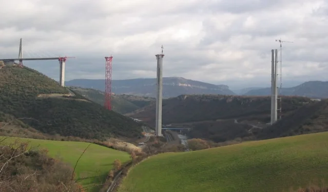
Pile construction began in January 2002, immediately after the December 2001 groundbreaking ceremony. By March 2002, the first pier shafts were emerging from ground level. The pier construction method was PERI GmbH's climbing formwork system — a self-jacking shuttering assembly anchored to the pier core. 1 As each concrete pour cured, the formwork anchor shoes climbed upward along rails cast into the pier walls, repositioned for the next lift, and the cycle repeated. This system allowed a 4-metre gain in pier height every three days, with fresh concrete placed approximately every 20 minutes per lift. 1 At that rate, a pier like P2 — rising nearly 245 m — required roughly six months of continuous formwork climbing.
The total concrete volume in the pier shafts alone was 53,000 m³, with a further 13,000 m³ in the foundation pile caps, 6,000 m³ in the bored piles, and 7,500 m³ in temporary works — a project total of approximately 127,000 m³ of structural concrete. 2 All seven pier shafts reached their full design heights by November 2003, 22 months after pile construction began.
The construction schedule also ran into the 2003 European heat wave. Summer temperatures in the Tarn valley exceeded 40°C, and sustained high temperatures prevent concrete from curing with the homogeneity that structural performance demands. Certain welding operations for the steel deck similarly had to be suspended during the worst of the heat. Some winter months also halted outdoor concrete work. Despite these interruptions, the schedule held.
Millau Viaduct under construction — south-side deck launching, 2004
Deck sections pushed from the south plateau approach the completed pier heads; the temporary hydraulic sliding bearings on each pier head are visible at the deck-pier interface 1

Launching 36,000 tonnes across a gorge

With the pier shafts complete, the project faced its most technically novel challenge: placing 36,000 tonnes of steel deck across a 2,460-metre span, in sections, without any ground-level falsework — conventional scaffolding from the valley floor being impossible at 270 m height.
The solution was incremental launching, a technique used on shorter viaducts but never before at the Millau scale and pier height. Steel deck sections were fabricated in a temporary assembly yard on each plateau — the north plateau at Brusque, the south plateau near Millau — and welded into a continuously growing cantilever extending outward from each end. The growing cantilever slides on temporary hydraulic sliding bearings sitting on each pier head, which were fitted with 64 temporary pylon supports (small steel columns, nicknamed béquilles, standing on the pier heads to provide intermediate support as the 342-metre spans were crossed). 1 Eight additional temporary towers were erected at pier head level to support the deck during the launching phases where the cantilever tip was in mid-span, too far from the next pier for the structure to be self-supporting. 1
The pushing mechanism was designed by Greisch Ingénierie and Enerpac (a US hydraulic tools manufacturer) — a computerised hydraulic wedge system. 1 In each cycle: a lower wedge slides under the upper wedge beneath the deck; the wedge pair lifts the deck fractionally off the bearing; both wedges advance together, carrying the deck forward; the lower wedge retracts; the upper wedge settles back onto the bearing; the lower wedge repositions for the next cycle. Each cycle takes 4 minutes and advances the deck 600 mm. 1 The deck crept forward at roughly 150–180 m per month from both ends simultaneously.
Precision was critical. A 36,000-tonne steel structure advancing over 245-metre pier heads in a mountain valley has limited tolerance for error: any lateral misalignment at the sliding bearing could impose transverse loads the temporarily unsupported pier would not be designed to handle. The guidance system combined GPS satellite positioning and laser alignment beams, with real-time feedback to the hydraulic control computers. 1 Even so, on the nights of 4–5 April 2004, when the advancing south cantilever had already covered 1,947 m, a combination of wind gusts and fog in the valley interfered with the laser guidance signals, and the pushing rate had to be reduced until conditions stabilised. 1
The north and south cantilevers met and were connected at P3/P4 mid-span on 28 May 2004 — the structural closure of the deck. 1 After closure, the temporary pylon supports and temporary towers were removed, the permanent bearings installed, and the deck lowered onto them.
The seven steel masts were assembled horizontally in a marshalling yard behind each abutment, then carried to their final positions on the deck using Kamag self-propelled modular transporter (SPMT) vehicles. Each mast, weighing approximately 650 tonnes, was then raised from horizontal to vertical in a single controlled rotation using temporary steel A-frame structures and hydraulic jacks. 1 Freyssinet (a Vinci group subsidiary) installed and tensioned all 154 stay cables.
The bridge opened to traffic on 16 December 2004 — 37 days ahead of its contracted date of 10 January 2005. 1 Total construction time from groundbreaking to opening: 38 months. Zero construction fatalities were recorded during those 38 months — building a 290,000-tonne structure at heights up to 343 m without a single fatal accident. 2

Technical specifications

正在加载统计卡片…
The deck plan incorporates a 20-kilometre horizontal curve radius — a slight curvature that improves sightlines and reduces the abruptness of the transition from the plateau approach roads. 1 The gradient of 3.025% is continuous from the north abutment to the south, matching the altitude difference between the two plateaux. 1
The 154 stay cables are each composed of between 55 and 91 individual 15-mm strands, depending on their position and load. 2 Three layers of corrosion protection were applied: hot-dip galvanising of individual wires, a petroleum-wax filler coating, and extruded high-density polyethylene outer sheaths. The outer sheaths carry double helical ribs — a detail that disrupts the rain-wind-induced vibration that can occur when water films form on smooth cable surfaces in crosswind conditions.
The bridge carries an embedded structural health monitoring (SHM) network: 12 fibre-optic extensometers at the base of P2 measuring micrometre-scale displacement, additional electrical extensometers at P2 and P7 sampling at 100 Hz, accelerometers at strategic deck positions, anemometers for live wind speed data, and piezoelectric sensors that classify vehicle type across 14 categories. 1 All data transmit via 20 km of fibre-optic cable to a management building adjacent to the toll plaza. The monitoring infrastructure also includes 30 km of high-voltage cable, 10 km of low-voltage cable, and 357 telephone access points distributed across the deck, pier shafts, and masts.
Road maintenance has proceeded on schedule. The original wearing course was replaced in September–October 2022 (4,600 tonnes of new asphalt) and a follow-up night-time resurfacing programme ran in May 2025. 4 Anti-corrosion treatment of the deck soffits, cable sheathing, and pylon feet has been running in cycles since the bridge opened, with work on the deck edge cornices restarted in 2023.

Legacy — 21 years at the top, and what came after

In September 2006, the International Association for Bridge and Structural Engineering (IABSE) presented the Millau Viaduct with its Outstanding Structure Award, citing "an elegant, slender bridge soaring above a deep valley connecting two plateaux which was constructed using an innovative launching procedure which advanced the state of practice in bridge construction." 5 The citation identifies exactly what the engineering community found transferable: not the height record, but the combination of ultra-tall pier construction with incremental deck launching at that scale. Both techniques existed before Millau, but the project demonstrated they could be combined, with GPS-laser guidance, to build spans of 342 m at pier heights up to 245 m within a 38-month schedule.
Norman Foster, whose architectural office provided the aesthetic framework within which Virlogeux's structural concept was realised, described the build-up as "an extraordinary experience." 6 Jacques Godfrain, then Mayor of Millau, drew the comparison that local politics demanded: "When they built the Eiffel Tower there were some people against it and at the time they engaged to destroy it. But today if you want to destroy the Eiffel Tower nobody would support you." 7 The viaduct had been controversial during planning because the gorge landscape was a significant tourist asset; the concern was that a road bridge would industrialise a natural scene. The completed structure largely resolved that argument: the slender white piers became a visual feature that draws visitors rather than repelling them.
The most concrete influence on subsequent bridge engineering is in the category of very-tall-pier, long-span cable-stayed structures. The Millau Viaduct demonstrated that pier heights in the 200–250 m range are constructionally achievable in reasonable schedules and that the aerodynamic deck solution — a thin steel-box section with an inverted-aerofoil cross-section — can be adapted to a range of wind environments. Several long-span viaducts in China built after 2004, including those in the Guizhou karst plateau, adopted similar incremental launching procedures and thin steel-box deck sections, acknowledging Millau as a reference project.
The height record itself has now been superseded. China's Changtai Yangtze River Bridge, which opened on 9 September 2025, reaches a structural height of 352 metres — 9 metres taller than Millau's 343 m mast tip. 3 The Changtai bridge is a double-deck cable-stayed structure with a 1,176-metre main span — simultaneously the world's tallest bridge structure and the world's longest cable-stayed span, surpassing the Russky Bridge (1,104 m) that had held the span record. 3
MetricMillau Viaduct (2004)Changtai Yangtze River Bridge (2025)
Structural height343 m (mast tip above ground)352 m
Tallest pier (to deck)244.96 m (P2)Not publicly disclosed
Main span342 m1,176 m
Total length2,460 m10,030 m
Deck typeSingle-level, 2 carriagewaysDouble-deck (road upper, road lower + rail planned)
Structural typeMulti-span cable-stayed, 7 piersCable-stayed, single main span
Construction cost€394 millionNot yet publicly disclosed
Sources: 1 3
In December 2024, the Compagnie Eiffage du Viaduc de Millau (CEVM) — the concession company operating the bridge — marked the 20th anniversary of the opening with 20 days of public celebrations, including collaborations with two local Aveyron craft manufacturers: Forge de Laguiole produced a limited-edition numbered knife series with handles made from PMMA windshield panels removed from the bridge during routine maintenance, and Maison Fabre Gantier produced a driving-glove capsule collection carrying the bridge's silhouette. 8 9
正在加载内容卡片…
The bridge's toll concession runs to 2079, with an earliest government buyback option in 2044 if revenues exceed projections. As of February 2026, toll charges for a standard car are €11.30 off-peak (mid-September to mid-June) and €13.80 in peak season (mid-June to mid-September). 4 The concession structure has proved financially stable enough that CEVM continues to invest in maintenance, including a maintenance technician recruitment in January 2026 whose job advertisement characterised working at Millau as "contributing to the life of a monument." 10
P2 pier and mast height comparison with the Eiffel Tower
The P2 pier rises 244.96 m to the road deck; the steel mast above it adds 88.92 m, placing the mast tip at 343 m above the valley floor — above the Eiffel Tower's 330 m tip 1
The structural record has moved to Changtai, but the engineering argument that Millau settled remains intact: a multi-span cable-stayed viaduct can be built across a 2,460-metre gorge with piers approaching 245 m, in 38 months, at a cost well under €400 million, using incremental launching, GPS-guided precision, and a thin aerodynamic steel deck — and it can do so without a fatality. That combination of scale, speed, safety, and precision is the benchmark the IABSE citation was pointing at. The height record is a number. The method is a template.
Cover image: Millau Viaduct panorama (2005), Wikimedia Commons

围绕这条内容继续补充观点或上下文。

  • 登录后可发表评论。