Space Shuttle Main Engine: the 30-year cost of flying the impossible

Space Shuttle Main Engine: the 30-year cost of flying the impossible

A 4,675-word case study of the RS-25 / Space Shuttle Main Engine — the highest-chamber-pressure liquid-propellant rocket engine ever flown operationally (2,994 psi). Covers NASA's 1971 staged-combustion decision, the turbopump development crisis (HPFTP at 35,360 rpm, 71,140 hp), the NARloy-Z combustion liner surviving 3,300 °C gas, the failed 55-mission reusability target, and the pivot to the expendable RS-25E powering SLS today.

Engineering Marvel Teardown
2026/5/26 · 2:12
4 订阅 · 8 内容
In the entire history of liquid-propellant rocketry, no flight engine has operated at higher chamber pressure than the Space Shuttle Main Engine (SSME). Its 2,994 psi (20.64 MPa) combustion chamber — a figure confirmed independently by Wikipedia and Encyclopedia Astronautica — exceeded the next closest competitors by a margin that had seemed physically unreachable when the contract was signed in 1971. 1 2
That number is the headline, but it obscures the actual story. Mark Wade, the author of Encyclopedia Astronautica, called the SSME "a technological bridge too far — the specified weight, reliability, durability, and reusability simply could not be met in a single engine using existing or foreseen technology and materials." 2 What followed was roughly three decades of engineering revision — turbopumps that failed on test stands, chamber pressures that destroyed hardware, and a reusability program that required dismantling the engine after every flight rather than flying it again.
This is a case study in what it costs to be first.

The brief that started the argument

The SSME's design requirements emerged from the Nixon administration's 1970–1972 planning process for what would become the Space Shuttle. The Space Activities Data and Information Exchange (SADIE) study established the mission architecture: a fully reusable system, low per-flight costs, and an engine capable of deep throttling so the crew could survive a two-engine-out abort at max-Q. 1
NASA issued its request for proposals in 1970 with a specific goal in mind. Rather than building on the existing F-1 or J-2 heritage at moderate chamber pressure, NASA wanted to — as the 1970 RFP stated — "force an advancement of rocket engine technology." 1 The target was approximately 3,000 psi chamber pressure, more than three times the operating pressure of the J-2 (the Saturn V upper-stage engine, then America's largest hydrogen engine) and nearly double the XLR-129 that Pratt & Whitney had already demonstrated. 1
Pratt & Whitney's XLR-129, a 250,000 lbf-class engine with a two-position variable nozzle, was the conservative choice. It was already working hardware. Rocketdyne's competing concept, built on experience from the HG-3 high-pressure research engine — itself a cancelled upgrade for the Saturn V — proposed the riskier, higher-performing option. NASA selected Rocketdyne on July 13, 1971, a decision that Pratt & Whitney immediately challenged through legal proceedings. Substantive development work did not begin until March 31, 1972. 1
By March 1977, the first complete engine (serial number 0002) had been assembled and fired at Rocketdyne's Canoga Park facility in California. Before STS-1 lifted off on April 12, 1981, the SSME program had accumulated 110,253 seconds of ground test time — well above NASA's required threshold of 65,000 seconds. 1 Those tests had also revealed something important: nearly every major subsystem had design problems that needed to be fixed.

Staged combustion: the cycle that changes everything

The choice of propulsion cycle was not obvious in 1970. Three main options existed: the gas-generator cycle, the expander cycle, and the staged combustion cycle.
In a gas-generator cycle (used by the F-1, the RS-68, and most Russian kerosene engines), a small portion of propellant is burned in a dedicated gas generator, its combustion products drive the turbopumps, and then that exhaust is dumped overboard. The efficiency penalty is modest but real: a fraction of your propellant never reaches the main chamber. The J-2 used a gas-generator cycle and achieved a vacuum specific impulse of 421 seconds. 3
In a staged combustion cycle, all propellant flows through the turbines and then into the main combustion chamber. Nothing is dumped overboard. The thermodynamic efficiency gain is substantial, but the engineering consequences are severe: the turbines must run on partially combusted propellant from preburners at extremely high temperatures and pressures, and the entire propellant flow is at high pressure simultaneously — which dramatically increases the demands on seals, valves, and structural members throughout the engine. 4
Rocketdyne's specific implementation chose fuel-rich staged combustion with a dual-shaft architecture. Rather than one preburner driving both turbopumps, the SSME uses two separate preburners — one for the High-Pressure Oxidizer Turbopump (HPOTP), one for the High-Pressure Fuel Turbopump (HPFTP) — each burning a small fraction of liquid oxygen with the full hydrogen flow, producing hot fuel-rich gas that drives its respective turbine. This twin-shaft arrangement allows independent control of both pumps, which matters because liquid hydrogen and liquid oxygen have very different densities and require different pressure ratios to reach the main chamber at the correct mixture ratio. 1
After driving their turbines, the hot fuel-rich exhaust from both preburners flows into the hot-gas manifold, where it mixes and is injected into the main combustion chamber alongside the remaining liquid oxygen. That final burn completes combustion. Because every kilogram of propellant eventually reaches the main chamber, the cycle's thermodynamic efficiency is near-theoretical — the RS-25D achieves 452.3 seconds of vacuum specific impulse, compared to 421 seconds for the gas-generator J-2 and 410 seconds for the gas-generator RS-68. 1 5
Throttle control in the SSME is managed through the oxidizer and fuel preburner oxidizer valves, which regulate the LOX flow to each preburner. Reducing LOX to the preburners reduces turbine power output, slowing both high-pressure pumps and reducing propellant mass flow — and therefore thrust. The system controls both turbopumps independently while maintaining the 6.03:1 LOX/LH2 mixture ratio in the main chamber through coordinated adjustment of the Main Oxidizer Valve (MOV) and Main Fuel Valve (MFV). The RS-25D can throttle from 67% to 109% of rated power level in 1% increments, a range that was essential for the Shuttle mission profile: throttle down at max-Q (roughly T+40 seconds) to reduce aerodynamic loads on the stack, then back up to full power, then down again as propellant depletes to hold acceleration below 3 g. 1
The critical design review for the SSME cycle was finalized by September 1976. The engineers who signed off on it understood the physics clearly. They were less certain they could manufacture hardware that would survive it.

The turbopump problem

No part of the SSME caused more development trouble than the turbopumps. "Components tests," Wikipedia notes with characteristic understatement, "identified deficiencies in several design areas — including the HPFTP." 1 NASA NTRS records document at least 38 technical papers on SSME turbopump failure modes filed between the 1970s and 1990s, covering topics from rotordynamic instability to bearing failures and duct fractures. 6
The operating conditions explain why. The HPFTP (High-Pressure Fuel Turbopump) is a three-stage centrifugal pump driven by a two-stage hot-gas turbine. It spins at approximately 35,360 rpm — faster than a Formula 1 engine at redline — and produces 71,140 horsepower (53.0 MW). 1 Its job is to take liquid hydrogen arriving at 1.9 MPa (276 psia) and deliver it at 45 MPa (6,515 psia) — a 23-fold pressure increase in a machine roughly the size of a large domestic refrigerator (approximately 550 × 1,100 mm). 1 The working fluid is liquid hydrogen at −253 °C (−423 °F). The turbine inlet gas is hot fuel-rich combustion product at temperatures exceeding 1,000 °C. Both conditions exist simultaneously in a component that must survive at least one human spaceflight and, in theory, 54 more.
The HPOTP (High-Pressure Oxidizer Turbopump) is structurally distinct: two single-stage centrifugal pumps — a main pump and a preburner pump — on a common shaft driven by a two-stage turbine. At approximately 28,120 rpm, it produces 23,260 horsepower (17.3 MW) and raises LOX pressure from 2.9 MPa to 30 MPa in the main stage, then to 51 MPa in the preburner stage. 1 The HPOTP faces a safety problem with no parallel in any other turbomachine: its turbine section runs on hot fuel-rich gas, while its pump section handles liquid oxygen. Any contact between those two streams is catastrophic. The engineering solution is a continuously helium-purged cavity separating the two sections; loss of helium pressure triggers an automatic engine shutdown. 1
To appreciate the scale of the turbopump challenge, consider what "35,360 rpm" requires in practice. Bearing steel rotating at that speed in liquid hydrogen — a fluid that is simultaneously an excellent coolant and a terrible lubricant — cannot use conventional oil lubrication. Early SSME turbopumps relied on metal roller bearings running without any lubricant, bathed in the propellant itself. Metal-on-metal contact at cryogenic temperatures and extreme speeds produced microscopic wear particles, subsynchronous vibration modes, and bearing failure patterns that destroyed hardware on test stands repeatedly through the 1970s. NASA's NTRS archive contains papers specifically addressing rotordynamic instability in the HPFTP — the condition where the rotor's whirling frequency locks into a fraction of the shaft speed, generating oscillating forces that bypass the bearing system and load the structure destructively. 6
The Block I upgrade, first flown on STS-70 in 1995, addressed a cascade of turbopump failure modes accumulated over 14 years of Shuttle operations. Ceramic bearings replaced metal bearings in both turbopumps — reducing the number of rotating parts by roughly half and eliminating metal-on-metal contact in the cryogenic environment. Silicon nitride ceramic has roughly one-third the density of steel, reducing centrifugal loads on the bearing races dramatically at high RPM, and it is harder and more chemically inert than steel in the LOX environment. New casting processes cut the weld count, reducing stress concentration sites. A new two-duct powerhead replaced the earlier single-duct design. 1 The Block IIA upgrade (STS-89, 1998) introduced a large-throat main combustion chamber that Rocketdyne had proposed as early as 1980 but that only became standard hardware 18 years into the program. The Block II RS-25D (STS-104, 2001) added a completely new HPFTP, ground-tested to 111% rated power level before being certified to 109%. 1
正在加载统计卡片…

The combustion chamber frontier

High chamber pressure is desirable because it allows more efficient combustion in a smaller volume, raises the thermodynamic cycle efficiency, and — combined with a large nozzle expansion ratio — increases specific impulse. Every pound of increase in chamber pressure is free specific impulse, in principle. The engineering penalty is that every subsystem must operate at proportionally higher stress.
At 3,000 psi, the combustion gas temperature inside the main combustion chamber (MCC) reaches 3,300 °C (6,000 °F) — above the boiling point of iron. 1 The wall between that gas and structural integrity is a few centimeters of alloy. Rocketdyne solved this with a material specifically created for the engine: NARloy-Z, a copper-silver-zirconium alloy developed in the 1970s whose primary virtue is copper's extremely high thermal conductivity. 1 Copper conducts heat roughly six times faster than stainless steel, rapidly transferring combustion heat into the regenerative cooling flow before the liner can melt. The MCC's structural shell is Inconel 718, a nickel-based superalloy that provides the high-temperature load-bearing capacity the copper liner cannot. 1
Approximately 390 channels are machined into the NARloy-Z liner wall. 1 Liquid hydrogen at −253 °C (−423 °F) flows through these channels before entering the combustion process, simultaneously cooling the liner and warming itself for injection. The temperature gradient across the channel wall in steady-state operation — from roughly −200 °C on the coolant side to over 500 °C on the gas side — represents one of the steepest sustained thermal gradients in any operational machine. Each engine start subjects the MCC to a thermal shock as the chamber goes from ambient to full operating temperature in under three seconds.
The mixture ratio selection reinforces the chamber's survival. Running the engine fuel-rich at 6.03:1 LOX/LH2 (versus the theoretical stoichiometric ratio of approximately 8:1 for hydrogen combustion) produces slightly cooler combustion products and a larger fraction of unburned hydrogen in the turbine exhaust. 1 That excess hydrogen is an excellent regenerative coolant — low viscosity, high heat capacity, and stable under the thermal conditions it encounters in the wall channels. A more oxidizer-rich mixture would increase combustion temperature and reduce cooling margin simultaneously. The 6.03 figure is a compromise that buys thermal survivability at a modest Isp penalty.

Nozzle geometry and the separation problem

At the nozzle exit, the RS-25's geometry creates a problem that no previous flight engine had faced at this scale. The nozzle expansion ratio — approximately 77.5:1 per Encyclopedia Astronautica (Aerojet Rocketdyne cites 78:1 for some configurations) — is unusually large for the engine's chamber pressure. 2 1 A nozzle of this ratio at sea level would normally experience flow separation — the supersonic exhaust detaches from the nozzle wall before reaching the exit plane, a condition that causes severe side loads and structural damage.
Rocketdyne's solution was geometric: rather than designing the nozzle wall as a smooth theoretical contour, engineers reduced the wall angle near the exit to raise the local pressure at the nozzle rim to 4.6–5.7 psi absolute. 1 The inner flow core operates near 2 psi, but the elevated rim pressure prevents the boundary-layer separation that would otherwise occur. The penalty is a slight departure from optimal nozzle efficiency, acceptable given the alternative.
The nozzle itself — 121 inches (3.1 m) long with a 90.7-inch (2.3-m) exit diameter — is cooled by liquid hydrogen flowing through brazed stainless steel tube passages in the nozzle wall. 1 The external surface carries four layers of metallic batting under metallic foil, providing thermal protection against launch, ascent, orbital, and reentry heating. A chamber coolant valve regulates gaseous hydrogen bypassing the nozzle cooling loop, managing nozzle wall temperature across the throttle range.
A note on conflicting source data: the task brief mentions "1,080 electroformed nickel cooling channels" for the engine. The Wikipedia and Encyclopedia Astronautica sources consistently describe approximately 390 machined channels in the NARloy-Z MCC liner and separately mention brazed stainless steel tube passages in the nozzle. The "1,080" figure may refer to an earlier design iteration, a combined channel count across both MCC and nozzle subsections, or a detail from Rocketdyne proprietary manufacturing documents not reflected in open-source literature. The 390 MCC-liner channel count is the figure supported by multiple independent sources and is used here; the discrepancy is noted for completeness.
The nozzle's outer thermal protection addresses a different set of problems: not structural heat flux but the mixed thermal environments the engine encounters across a mission. Launch pad acoustic and flame trench heating, Mach 25 aerodynamic heating on ascent, deep cold soaking in orbit, and reentry heat on the orbiter's aft end each impose different temperature rates and directions through the nozzle wall. Four layers of metallic batting under metallic foil provide passive insulation that absorbs these transients without requiring active thermal management on the exterior surface — a detail that looks trivial compared to the regenerative cooling system but represents a real engineering problem when the same hardware must survive radically different thermal boundary conditions over the course of a single mission.

Reusability: the goal that drove everything and fell short

Artemis I rollout (November 2022): four RS-25 engines — originally flown on Shuttle missions — visible at the base of the SLS core stage. 7
The SSME's original design specification called for 55 missions between major overhaul — the engine should fly more than a year of weekly Shuttle flights before requiring disassembly. The vacuum Isp target was 455 seconds. 2 Neither goal was fully achieved. The actual vacuum Isp reached 452.3 seconds. And every single Shuttle flight ended with the three RS-25 engines being removed from the orbiter, transported to the SSME Processing Facility, inspected component by component, refurbished as required, and recertified for flight. 1
The maximum demonstrated reuse for any single engine was approximately 27 flights — less than half the 55-mission target. 1 In practice, engines were not limited by hours or cycles but by the accumulation of inspection findings: cracks in turbine blade coatings, wear in seals, dimensional changes in high-cycle-fatigue components. The cost of inspection and refurbishment was substantial. At roughly $40 million per engine (in Shuttle-era dollars), a cluster of three engines represented $120 million of hardware that was being partially rebuilt after every flight. 1
Wade's verdict on this outcome is characteristically direct: "In the end, the shuttle proved to be a very expensive method of recovering reusable engines that perhaps cost more than expendable ones." 2 The economic logic of reusability assumed that recovery and refurbishment would cost substantially less than manufacturing new engines. Given the inspection intensity the SSME required after each flight, that assumption did not hold.
Across 135 missions and 405 individual engine-missions, the RS-25 achieved a flight reliability of 99.95% per Pratt & Whitney Rocketdyne's reporting. 1 The single confirmed in-flight shutdown occurred on STS-51-F (Challenger, July 1985): Engine 1 (serial 2023) shut down at T+5:43 due to a faulty temperature sensor reading, forcing an abort-to-orbit trajectory that still successfully completed the mission. 1 The engine itself had no fault.
The STS-93 (Columbia, July 1999) incident illustrates how the engine's margin could be consumed by unrelated hardware. A gold-plated pin measuring approximately 0.1 inches in diameter and 1 inch long — used to plug an oxidizer post hole — dislodged from the main injector assembly and struck the nozzle inner surface. It punctured three hydrogen coolant tubes in the nozzle wall, causing a hydrogen leak that increased fuel consumption and led to a slightly early main engine cutoff. The resulting velocity deficit of 16 ft/s left Columbia in an orbit roughly 8 nautical miles lower than planned. 1 The crew and mission were unaffected. But the incident exposed an injector assembly retention detail that had been cleared in design review and demonstrated in testing — and still failed.
The SSME's reliability record is, by the numbers, genuinely remarkable. The 99.95% figure across 405 engine-missions represents a standard that very few propulsion systems have approached. The point is not that the engine was unreliable — it was not. The point is that achieving that reliability at this chamber pressure and with this cycle complexity required a level of post-flight inspection and refurbishment that redefined what "reusable" meant in practice.
It is worth noting what 99.95% means in statistical terms for a crewed program. That rate implies roughly one failure per 2,000 engine-missions. With three engines per flight, the probability of at least one engine anomaly per flight is approximately one in 667 — still far higher than the per-flight reliability implied by a simple reading of the percentage. The redundancy built into the Shuttle's three-engine design was not decorative; it was load-bearing. The engine was designed to complete its mission after a single-engine-out event at any point after throttle-down at max-Q, which explains why the 67% lower throttle bound was not merely a performance floor but a structural abort boundary.

From Shuttle to Artemis: the Block evolution and the SLS pivot

正在加载图表…
The SSME's 30-year operational history is a sequence of block upgrades, each addressing failures found in service rather than anticipated in design. The trajectory from the original 100% rated power level (RPL) certification on STS-1 to the 113% contingency capability of the RS-25E development engine reflects both the engine's fundamental design margin and the accumulation of targeted fixes.
The baseline FMOF (First Manned Orbital Flight) configuration — engines 2005, 2006, and 2007 on STS-1 through STS-5 — was certified at 100% RPL. 1 Phase I (STS-6 through STS-51-L) raised certification to 104%. After Challenger's STS-51-L accident in January 1986, Phase II (RS-25A) introduced safety upgrades and established the 104%/109% normal/contingency split that would persist through most of the Shuttle program.
Block I (RS-25B, STS-70, 1995) was the major mechanical overhaul: ceramic bearings in turbopumps, redesigned casting processes to reduce weld counts, new two-duct powerhead. Block IA added main injector improvements. Block IIA (RS-25C, STS-89, 1998) introduced the large-throat MCC — a combustion chamber modification Rocketdyne had proposed eighteen years earlier. 1 The Block IIA also brought improved low-pressure turbopumps and certification to 104.5% RPL.
Block II (RS-25D, STS-104, 2001) completed the upgrade cycle with a new HPFTP, ground-tested to 111% and certified to 109% for intact-abort use. 1 This is the configuration that flew the final 34 Shuttle missions and powered Artemis I's SLS core stage on November 16, 2022 — the engine's first flight after eleven years in storage.
The SLS pivot changed the economic calculus fundamentally. On SLS, the RS-25D is expendable: four engines per flight, burned and discarded with the core stage. The argument for reusability — the entire rationale that drove the SSME's design complexity and cost — was set aside for a vehicle architecture that cannot recover its first stage. 1 The first four Artemis flights consume the sixteen RS-25D engines stored at Stennis Space Center since STS-135's retirement in 2011.
When those engines are gone, the RS-25E takes over. Designed explicitly for one-time use, its powerhead has been "almost completely redesigned" according to Wikipedia, with manufacturing innovations that Aerojet Rocketdyne (now L3Harris Technologies) reports cut powerhead manufacturing time by 15% and main combustion chamber production cycle by 22 months. 1 The RS-25E development engine E10001 passed full qualification testing; the 12-test certification series for unit E0525 ran from October 2023 through April 2024. The first production RS-25E (E20001) completed a 500-second hot-fire test at Stennis at 111% power on June 20, 2025. 8 A second production engine (E20002) completed the same test profile on November 12, 2025. 1
The contract covering 18 additional RS-25 engines for SLS, awarded in May 2020, extended the total SLS contract value to approximately $3.5 billion. 1 L3Harris Technologies acquired Aerojet Rocketdyne — the RS-25's manufacturer through the Shuttle era — in July 2023 for $4.7 billion. As of 2026, L3Harris plans to divest the space propulsion division to AE Industrial Partners, which would reconstitute it under the Rocketdyne name. 9
The peculiar irony of the RS-25E is that the expendable version of a reusability-driven engine is cheaper to manufacture, faster to build, and more powerful than the reusable version it replaces — not because the original engineers failed, but because eliminating the refurbishment infrastructure allows manufacturing trade-offs that were previously off-limits.

Engineering legacy: what SSME taught the world

The SSME produced measurable changes to propulsion engineering practice, though not always in the direction its designers anticipated.
Materials. NARloy-Z, the copper-silver-zirconium alloy developed specifically for the SSME's main combustion chamber, entered the materials engineering canon as a reference case for high-heat-flux applications in cryogenic-to-hypersonic environments. The combination of copper's thermal conductivity with enough structural reinforcement to survive chamber pressures above 20 MPa had not previously been demonstrated in flight hardware. NASA has since studied applying thermal barrier coatings (TBC) and ceramic matrix composites (CMC) to future RS-25 derivative combustion chambers, potentially enabling even higher heat loads with reduced coolant flow. 1
The staged-combustion benchmark. Wade describes the SSME as "the only high-pressure closed-cycle reusable cryogenic rocket engine ever flown." 2 That phrasing loads several important distinctions: high-pressure (above 200 bar), closed-cycle (staged combustion, not gas-generator), reusable (design-intent, if not fully realized in practice), and cryogenic (LOX/LH2 rather than storable propellants). The Soviet RD-180 and RD-170 achieved higher thrust in a different oxidizer-rich staged-combustion cycle, but none have combined all four of those attributes in a flight engine. The SSME's development laid out the engineering envelope — and its failure modes — for every subsequent high-pressure closed-cycle program.
The deliberate simplification. The RS-68, Rocketdyne's second LOX/LH2 rocket engine and a deliberate step back from the SSME's cycle complexity, makes the engineering trade-off legible. Designed for the Delta IV launch vehicle in the late 1990s, the RS-68 uses a gas-generator cycle — not staged combustion — and achieves a vacuum specific impulse of roughly 410 seconds — about 42 seconds below the RS-25D. 5 It has 80% fewer parts than the SSME and costs approximately $20 million per unit versus the SSME's $40 million. 5 The RS-68 uses an ablative nozzle rather than a regeneratively cooled one, accepting nozzle degradation in exchange for manufacturing simplicity. The trade-off is explicit and documented: every point of Isp the RS-68 gives up relative to the SSME represents a deliberate decision to reduce cost, parts count, and development risk at the expense of thermodynamic efficiency. The two engines are complementary existence proofs of the design space: the SSME defines the high-efficiency frontier; the RS-68 defines what you get when you optimize for affordability on the same propellant combination.
Controller survival. One of the least-cited technical achievements of the SSME program is the resilience of its dual-redundant engine control computers. The Honeywell HDC-601 controllers (later upgraded to quad-M68000 processor arrays) are installed directly on the engine, not in the orbiter's avionics bay. 1 After the Challenger accident in January 1986, recovery divers found the engines from STS-51-L on the Atlantic floor at depth. The two Main Engine Controllers from engines 2020 and 2021 were retrieved, disassembled, flushed with deionized water, vacuum-dried, and their non-volatile plated-wire memory was successfully read for forensic analysis. 1 The data recovered confirmed the engines had been performing normally at the moment of the external tank failure — a finding that clarified the accident sequence and influenced subsequent accident investigation methodology.
The SSME program's deepest legacy is perhaps a negative one: it demonstrated, at cost, that the combination of maximum performance, human-rated reliability, and genuine reusability cannot all be optimized simultaneously in a single engine with 1970s materials and manufacturing methods. Wade's framing — "a technological bridge too far" — is not a criticism of the engineers. It is a description of the state of the art. The engine they built was genuinely the most technically demanding liquid-propellant machine in the history of operational rocketry. The RS-25D that powered Artemis I in 2022 is recognizably the same design as the FMOF engine on STS-1 in 1981, progressively refined through 135 missions, five major block upgrades, and roughly 50 years of continuous engineering investment.
正在加载链接预览…
The question SLS raises — whether it was worth maintaining this engine lineage into the expendable era — has a straightforward engineering answer: the RS-25D engines already existed, already had human-rated reliability records, and could be refurbished for SLS use at a fraction of the cost of a clean-sheet design. The RS-25E production restart is the next chapter of that same calculation, now accounting for the fact that the engines will not return.
What the SSME ultimately left behind is not a reusable engine. It is a set of techniques, materials, failure modes, and engineering intuitions that define what is possible at the high end of liquid-propellant propulsion — and a cost accounting that every subsequent engine program has had to reckon with.

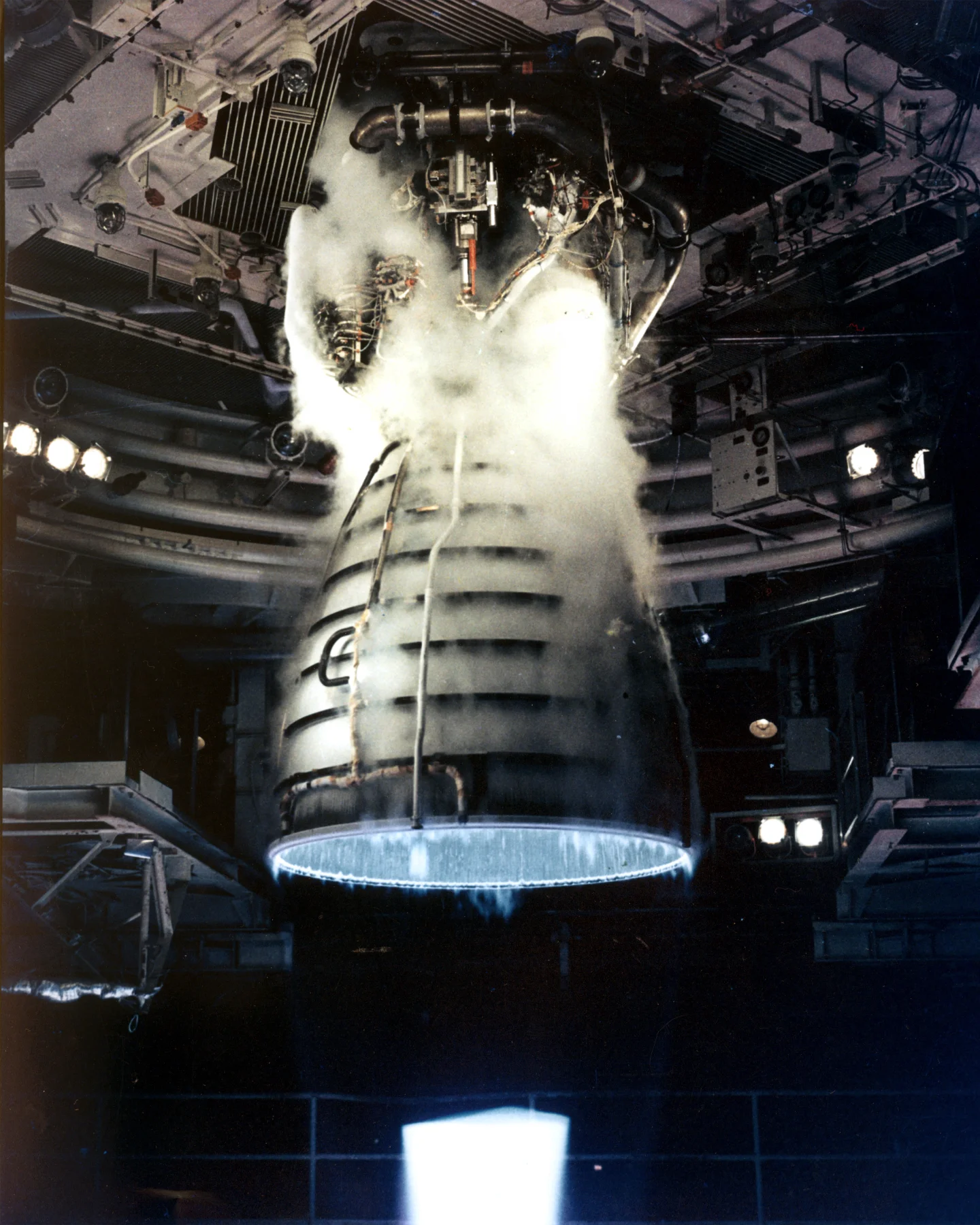
Cover image: RS-25 test firing at Stennis Space Center. Image from Wikimedia Commons (public domain, NASA)

围绕这条内容继续补充观点或上下文。

  • 登录后可发表评论。