www.faa.gov
Concorde: the engineering decisions that pushed aluminum to its absolute limit
Concorde's Mach 2.04 cruise speed was not a target — it was a hard constraint set by the thermal limit of RR58 aluminium. Every major engineering decision cascaded from that ceiling: the ogival delta wing that replaced slats with vortex lift; the variable intake ramps that contributed 63% of cruise thrust while the engines contributed just 8%; the CG fuel transfer system that replaced pitch trim surfaces at supersonic speed; and the flight mechanics of Air France Flight 4590 that grounded the fleet. The article traces nine interconnected engineering systems through their trade-off logic.

On 2 March 1969, André Turcat lifted Concorde 001 off the runway at Toulouse with the throttles wide open and all four Olympus engines in reheat. The aircraft climbed away subsonic and stayed that way for the entire 27-minute test hop. Nobody expected Mach 2 on the first flight. What Turcat and the engineers already knew was that every major system on the aircraft — the wing, the engines, the materials, the inlets, the fuel system, the flight controls — had been designed around a single unrelenting constraint: sustained cruise at Mach 2.04, a speed at which air friction heats aluminium to 127°C and the aircraft itself grows 300 mm in length. 1
The program that produced Concorde began with a bilateral treaty signed in November 1962 between the British and French governments, which locked both sides into a joint development they could not exit unilaterally. 1 The treaty was unusual in aerospace history: it committed both nations to a timetable before the engineering problems were solved. For the next decade, the engineers had to invent solutions in real time, working on a programme whose political inertia made cancellation harder than continuation. Twenty aircraft were eventually built; fourteen entered commercial service with British Airways and Air France, flying the North Atlantic from January 1976 until October 2003. What they left behind is a body of engineering decisions — each one the product of a specific trade-off — that still reads as one of the most concentrated examples of solving interconnected problems under hard physical constraints.
The ogival delta wing: solving low-speed lift without slats
Every conventional swept wing generates lift by accelerating airflow over the upper surface using leading-edge slats and trailing-edge flaps. The high-speed penalty for that approach is not immediately obvious, but at Mach 2 it becomes dominant: the thick, high-camber aerofoil sections required for slat-based lift create wave drag that is incompatible with efficient supersonic cruise.
The Concorde team's answer — developed theoretically by Johanna Weber and Dietrich Küchemann at the Royal Aircraft Establishment (RAE) in Farnborough during the 1950s — was the ogival (ogee) delta wing: a compound-curve planform whose leading edge sweeps from approximately 75° at the root to about 60° at the tip, tracing an S-shaped curve when seen from above. 1 The key insight was that a sharp, highly swept leading edge, when flown at a high angle of attack, does not produce attached flow. Instead, the flow separates immediately from the leading edge and rolls up into a pair of stable conical vortices running along the top surface. Those vortices carry momentum downward, creating a persistent low-pressure region — vortex lift — that supplements the conventional circulation-based lift without requiring any mechanical high-lift devices.
Test pilot Eric Brown recalled that when Küchemann presented this concept at a conference, Morien Morgan "immediately seized on it as the solution to the SST problem." 1 Weber later noted a reinforcing effect: "the lift from the vortex was increased by the length of the wing it had to operate over, which suggested that the effect would be maximised by extending the wing along the fuselage as far as possible." 1 This explains the ogee planform's blended fuselage integration — the wing root runs almost the full length of the fuselage, maximising the vortex path.
The Handley Page HP.115 research aircraft, flying from 1961, demonstrated that slender delta configurations could be controlled safely down to 69 mph (111 km/h) — roughly one-third the approach speed of contemporary combat aircraft with comparable span loading. 1 That result directly justified removing leading-edge slats from the production aircraft entirely, saving hundreds of kilograms and eliminating the structural complexity of leading-edge mechanisms that would have been subjected to repeated thermal cycling.
The aerodynamic trade-off is straightforward: at Mach 2.04 cruise, the ogival delta achieves a lift-to-drag ratio of about 7.14. That is modest — a subsonic airliner manages 15 to 20. But the point is not to maximise L/D in isolation; it is to achieve it at Mach 2 with an airframe light enough to carry enough fuel to cross the Atlantic. The wing's low thickness-to-chord ratio of approximately 3% simultaneously minimises wave drag at supersonic speed and provides enough internal volume to house the 119,500 litres (95,680 kg) of fuel the aircraft needs. 1 The fuel tanks are not bags inside the wing — the wing skin itself, stressed aluminium alloy machined to tolerances of fractions of a millimetre, forms the tank walls.
The unavoidable penalty at landing is a 12–15° angle of attack, which pitched the nose so far up that pilots could see nothing forward. That problem required its own solution.
Kinetic heating and RR58: the material that set the speed limit
Mach 2.04 is not an arbitrary number. It is the highest speed at which the Concorde airframe can fly indefinitely without the aluminium skin exceeding its safe operating temperature. The relationship is inescapable: at Mach 2, air stagnates against the forward surfaces of the aircraft, and the kinetic energy of that deceleration converts directly into heat. The stagnation temperature at Mach 2.04 at cruise altitude (51,000 ft / 15,500 m) is approximately 127°C (261°F) at the nose, dropping to about 91°C (196°F) at the tail. 2
Standard aircraft-grade aluminium alloys begin to lose yield strength above around 100°C under repeated thermal cycling. The Concorde programme needed an alloy that could sustain structural loads at 127°C across thousands of flight cycles lasting up to 3.5 hours each, with a target airframe service life of 45,000 flight hours. 1
The answer was Hiduminium RR58 (designated AU2GN in France), an aluminium-copper-magnesium-nickel alloy originally developed by High Duty Alloys Ltd for gas turbine compressor components during the Second World War. Its composition — 2.5% Cu, 1.5% Mg, 1.2% Ni, 1.0% Fe, 0.2% Si, 0.1% Ti, remainder aluminium — gives it superior creep resistance at elevated temperatures compared with conventional 2024 or 7075 series alloys. 2 Concorde was the first application of RR58 as large-area fuselage skin — a material that had previously been confined to small machined rotating parts now had to be cold-rolled into smooth sheet panels up to several metres in length.
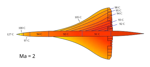
The 127°C thermal limit is what makes exceeding Mach 2.02 operationally unacceptable. At higher speeds, stagnation temperatures would push the aluminium into a regime where it softens faster than the service life calculations allow. That constraint also explains Concorde's mandatory white paint scheme: a high-reflectivity white finish reduces equilibrium skin temperature by 6–11°C compared with a darker livery — enough to extend fatigue life meaningfully. 1 The consequence of thermal expansion is visible to the crew. At cruise, the airframe grows 300 mm (12 inches) compared with its cold resting length. 1 The expansion manifests as a gap between the flight engineer's console and the forward bulkhead — wide enough to fit a hand. On the final retirement flights of both British Airways and Air France Concordes, engineers slipped their hats into the gap as a farewell ritual; when the aircraft cooled, the hat was permanently clamped in place.
The materials engineers also had to solve thermal expansion at a structural level. The fuselage could not simply be welded as a continuous shell — thermal joints at specific frame stations allow longitudinal growth to occur without buckling the skin or overloading the fasteners.
The variable intake ramps: where 63% of the thrust actually came from
Ask most people where a jet engine's thrust comes from and they will name the engine. On Concorde at Mach 2 cruise, that answer is wrong by a factor of seven.
At Mach 2.04 cruise, only 8% of the total propulsive force came directly from the engine's exhaust thrust. The intake system — the variable-geometry rectangular duct that sits upstream of each Olympus engine — contributed 63%. The variable secondary (exhaust) nozzle contributed the remaining 29%. 3 Former Concorde chief test pilot Brian Trubshaw confirmed the precise figures: "63% derived from forward pressure against structures inside the air intake system, and 28% from forward pressure against the exhaust nozzles." 3
The mechanics are straightforward in principle. Supersonic air arriving at the intake face must be decelerated to roughly Mach 0.5 before entering the compressor — supersonic compressors do not exist. Slowing the airflow from Mach 2 to Mach 0.5 compresses it by a factor of roughly 7.3:1 in the intake alone. 3 That compression generates enormous forward thrust on the intake internal surfaces — which is why managing the intake's shock structure correctly was worth more thrust than the engine itself.
The BAC-designed intake uses two moveable ramps and one spill door per engine nacelle to create a system of oblique shocks rather than a single normal shock. A single normal shock at Mach 2 would recover only about 72% of the total pressure; the Concorde intake achieves approximately 94% pressure recovery using a sequence of progressively weaker oblique shocks that deliver air to the compressor face with minimal entropy rise. 4
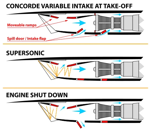
The ramps begin moving at Mach 1.3 and reach roughly half their travel by Mach 2.0. They are controlled by eight Air Intake Control Units (AICUs) — two per engine, Lane A and Lane B — of which at least seven must function for supersonic operations to continue. 4 In 1972, the original analogue AICUs were replaced with the first full-authority digital controllers used on any civil aircraft — a BAC Electronics and Space Systems development that preceded the term "FADEC" by more than a decade. The digital upgrade was essential: the analogue units lacked the precision to schedule the ramps tightly enough to prevent compressor surge under all throttle transients and temperature conditions.
If the intake is mis-scheduled — ramps at the wrong position for the prevailing Mach number — the oblique shock system collapses into a normal shock that sits downstream of the design point. The resulting pressure recovery loss generates so much intake drag that it exceeds the engine's net thrust, giving a net negative propulsive contribution from that nacelle. The consequence is what the Concorde engineers called an unstart: a violent pressure transient that yaws the aircraft and demands immediate crew action. In-service experience with unstarts was one of the most challenging aspects of early supersonic operations, and suppressing them was central to the AICU development programme.
The Olympus 593: why a turbojet and not a turbofan
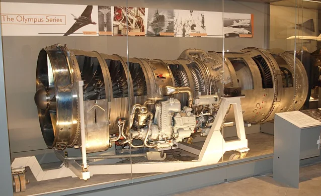
The Rolls-Royce/Snecma Olympus 593 Mk 610 is a two-spool (twin-shaft) turbojet with 7 low-pressure stages and 7 high-pressure stages in the compressor, each driven by a single turbine stage. The production variant produces 38,050 lbf (169.3 kN) wet thrust (with reheat) and 32,000 lbf (142 kN) dry thrust. 3 It is the direct descendant of the Bristol Olympus 22R that powered the Avro Vulcan strategic bomber at 11,000 lbf, developed through the Olympus 320 at 30,000 lbf that was intended for the cancelled TSR-2 strike aircraft. 5
The choice of turbojet over turbofan was not sentimental conservatism. Turbofans produce high thrust at low speed by accelerating a large mass of bypass air, but that large bypass fan has a significant frontal area. At Mach 2, wave drag scales with the square of the cross-section: a turbofan nacelle that is, say, 50% larger in diameter than a turbojet nacelle of equal core size generates roughly 2.25× the wave drag. Heritage Concorde's technical documentation states directly: "For optimum supersonic flight, turbofan engines were considered, but then rejected, this was due to their large master cross-section which would cause excessive drag." 5
The turbojet compensates by exhausting all its air through the core — a small, hot, fast jet. At Mach 2, the exhaust velocity only needs to exceed the flight velocity (about 1,150 mph / 1,850 km/h) to generate net thrust. A turbofan with high bypass ratio would exhaust its large secondary flow at low velocity, giving negative net thrust from the fan stream at supersonic speed.
The penalty, which the engineers accepted, is severe inefficiency at low speed and high noise on take-off. Concorde burns fuel at 15.8 passenger-miles per US gallon — compared with 46.4 for the Boeing 747 and 53.6 for the McDonnell Douglas DC-10 that operated the same trans-Atlantic routes. 1 The four Olympus 593s at take-off produced a combined 152,200 lbf and a noise signature that immediately became a regulatory problem at every airport the aircraft served.
The reheat system on the Olympus 593 is partial, not full military afterburning. Full afterburner on a military engine roughly doubles thrust (a 50% increase over dry). The Concorde reheat provides only 20% thrust increase — approximately 6,000 lbf per engine above dry thrust. 3 It is used only during take-off and the transonic acceleration phase between Mach 0.95 and Mach 1.7. Above Mach 1.7, intake ram compression is sufficient to enable the core to produce adequate thrust without supplemental fuel injection; Concorde cruises at Mach 2.04 with reheat off. This is genuine supercruise — sustained supersonic flight without afterburner — at a time when every military aircraft capable of Mach 2 needed full reheat to maintain it.
The thermodynamic efficiency at cruise is documented precisely. At Mach 2.02 cruise at 51,000 ft, the combined inlet-engine-nozzle system achieves an overall pressure ratio of 82:1 (7.3:1 from the intake, 11.3:1 from the engine) and a thermal efficiency of approximately 43% — measured by Sir Stanley Hooker (Rolls-Royce), who described it as "the highest figure recorded for any normal thermodynamic machine" at that time. 3 The Boeing 787's GEnX engine, with modern three-dimensional aerodynamic blade design and bypass ratio of 9.6, achieves an overall pressure ratio of about 58:1.
The SNECMA-developed secondary nozzle — the "eyelid" convergent-divergent exhaust system mounted at the aft fuselage — functions as a variable-geometry ejector, drawing secondary airflow bled from the intake's spill door and accelerating it together with the core exhaust. This ejector action accounts for the 29% thrust contribution from the nozzle. The eyelids also double as thrust reversers: at landing, they close to deflect the exhaust forward, providing braking from touch-down to taxi speed. 3
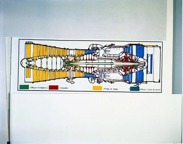
The Olympus 593's compressor uses titanium alloy for the forward stages (lower temperature) and Nimonic 90 nickel alloy for the final four high-pressure stages, where compressor delivery temperature reaches levels that titanium cannot sustain. High-pressure turbine blades are single-crystal nickel superalloy castings with 18 internal cooling channels fed by fifth-stage HP compressor bleed air, enabling a turbine entry temperature of approximately 1,450°C. 3 The overall pressure ratio and turbine entry temperature were both record-setting when the engine entered service.
Centre-of-gravity fuel transfer: 20 tonnes as an auxiliary trim surface
Every swept wing experiences an aerodynamic centre shift as it accelerates from subsonic to supersonic flight. For a conventional wing, this shift is modest and manageable with conventional trim surfaces. For Concorde's ogival delta, the aerodynamic centre moves 2 metres (6 ft 7 in) aft during the transonic transition from Mach 0.95 to Mach 2. 1
Countering a 2-metre aft shift with elevon trim would require holding the elevons deflected nose-up for the entire cruise phase. Elevon deflection creates drag, and at Mach 2, trim drag in the range of even 1–2% of total drag eliminates a large fraction of the route economics. The Concorde engineers rejected trim as the solution.
Instead, they used the aircraft's own fuel. During the transonic acceleration phase, approximately 20 tonnes of fuel is pumped from forward trim tanks (Tanks 9 and 10) to the rear trim tank (Tank 11, located aft of the rear pressure bulkhead) and to mid-fuselage collector tanks. 6 The centre of gravity moves aft by approximately 2 metres, tracking the aft movement of the aerodynamic centre. The aircraft remains in trim without any elevator input.
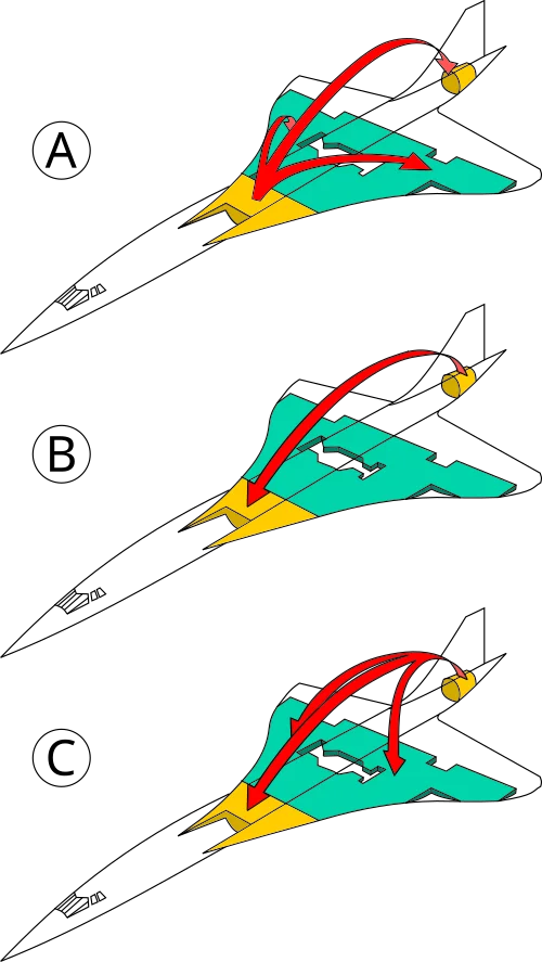
The reverse sequence — pumping fuel forward — occurs during deceleration and descent, restoring the CG to a position compatible with subsonic handling before landing. Tank 11 has four pumps for the aft-to-forward transfer: two electric (115V AC) and two hydraulic (driven by the Green and Yellow circuits), providing full redundancy in the direction that is critical for safe landing. 6 The system also operates as a side effect at take-off: the slightly aft CG position at departure causes the elevons to deflect down, increasing wing camber and providing a small incremental lift increase at a moment when lift is most needed.
Three independent CG indication systems — each with its own CG computer — display the aircraft's instantaneous centre of gravity and acceptable envelope limits referenced to Mach number on the same gauge. If a fuel transfer failure occurred and a pilot attempted to land with the CG too far aft, the aircraft would pitch up uncontrollably. The triple redundancy reflects that consequence.
Fly-by-wire and the droop nose: first of both
Concorde entered service in January 1976 as the world's first commercial aircraft with an analogue fly-by-wire flight control system. 7 "Analogue fly-by-wire" means that electrical signals generated by the pilot's control column replace the mechanical rods and cables of a conventional system — the pilot's inputs are transmitted as voltages, processed through an autostabiliser computer, and used to drive hydraulic actuators at each control surface.
The architecture uses three parallel channels: a Green electrical channel, a Blue electrical channel, and a mechanical backup. 7 In 27 years of commercial operations, the mechanical backup channel was never activated in flight — not once. 7 Six elevons (three per wing) and two rudder panels are each driven by their own independent Powered Flying Control Unit (PFCU) — an electro-hydraulic servo capable of drawing power from either the Blue or Green hydraulic circuit, with Yellow as standby. Hydraulic system pressure runs at 4,000 psi (28 MPa), higher than contemporary transport aircraft, to achieve the actuation speeds required for supersonic stability control. 8
The autostabiliser operates in all three axes simultaneously. In yaw, it provides automatic engine-failure compensation — if an outboard engine fails, the corresponding yaw moment is countered before the pilot has time to react. At Mach 2, the time constant for aircraft divergence is short enough that human reaction times are insufficient for manual correction alone.
There are no conventional pitch trim surfaces. Trim at supersonic speed is handled entirely by the CG fuel transfer system. Elevons trim only the residual pitch moments that remain after fuel transfer has positioned the CG correctly.
The droop nose addresses a straightforward visibility problem created by the ogival delta. The same high angle of attack that generates vortex lift at landing — roughly 12–18° — lifts the aircraft nose so far above the horizontal that the pilots cannot see the runway. Marshall Aerospace (Cambridge) designed a mechanism with four positions: 9
- Position 1 (nose up, visor up): supersonic cruise and ground parking
- Position 2 (nose up, visor down): short subsonic legs, windscreen cleaning
- Position 3 (nose down 5°, visor down): taxiing and take-off
- Position 4 (nose down 12.5°, visor down): landing approach
The glass visor, developed by Triplex, withstands sustained aerodynamic heating above 100°C in supersonic flight. The nose and visor are driven by separate hydraulic actuators with mechanical locks in each position; an emergency gravity-release mode allows the nose to droop freely if hydraulics are lost. The early prototype aircraft had no windscreen — just an all-metal nose — but the FAA refused to certify a transport aircraft in which the pilots literally could not see forward. The production visor was the result.
Sonic boom and the oceanic constraint
At Mach 2 cruise, Concorde generates a continuous N-wave pressure signature that sweeps a ground footprint approximately 90 km wide along the flight track, with an overpressure of about 1.94 psf (93 Pa) at ground level. 1 That overpressure is sufficient to rattle windows, alarm the public, and far exceeds any regulatory threshold for acceptable ground-level impulse noise. The United States, India, Malaysia and other nations prohibited supersonic overland flight by Concorde from the outset.
The consequence for route economics was severe. Concorde's only viable commercial markets were oceanic — London to New York, London to Bahrain, Paris to New York, Paris to Caracas. The sonic boom constraint, more than any single engineering failure, is what kept the production run at 20 aircraft rather than the 300-plus orders that the manufacturers originally projected. 1 Airlines across Asia, South America, and the domestic US market — all requiring overland legs — could not operate an aircraft that became subsonic the moment it crossed a coastline.
Concorde used dedicated SST (Supersonic Transport) tracks on the North Atlantic, fixed routes distinct from the standard NAT High-Level Airspace used by other aircraft. Unlike conventional transatlantic routing, which shifts daily to take advantage of or avoid the jet stream, the Concorde tracks were fixed: the aircraft's cruise altitude of 51,000–60,000 ft placed it well above the jet stream, making daily wind routing largely irrelevant. 1
The noise at take-off from all four Olympus 593s simultaneously was a separate and equally contentious problem. The aircraft departed London Heathrow and Paris Charles de Gaulle with selective noise-abatement procedures — retarding thrust after take-off, climbing steeply to clear the most densely populated approach corridors — that were bespoke to each airport and required pilots to manage a power reduction schedule while the aircraft was still accelerating.
Air France Flight 4590: how a 43 cm strip of titanium ended the programme
At 16:42 CEST on 25 July 2000, Air France Flight 4590 — Concorde F-BTSC — began its take-off roll on runway 26R at Charles de Gaulle Airport, bound for New York. On the runway lay a titanium alloy wear strip, approximately 435 mm × 30 mm × 1.4 mm, that had fallen from a Continental Airlines DC-10 (flight CO55, registration N13067) five minutes earlier. 10 The strip was not stainless steel as specified by its manufacturer — it had been improperly installed at a Houston maintenance facility on 9 July 2000 using the wrong material. 11
At approximately 300 km/h on the take-off roll, the Number 2 tyre on the left main gear bogie ran over the strip and burst. A 4.5 kg chunk of tyre debris struck the underside of the left wing at an estimated 140 m/s, directly above the Number 5 fuel tank. The Bureau d'Enquêtes et d'Analyses (BEA) investigation identified two simultaneous failure mechanisms: the "continuity effect" — skin deformation at the impact point creating outward rotation and strain in adjacent areas — and a hydrodynamic pressure surge within the completely full, incompressible-fluid-filled tank. 11 Tank 5 was 94% full of jet fuel at the moment of impact.
The BEA concluded this was "a type of failure never experienced before in the history of civil aviation." 11 A 32 cm × 32 cm panel of tank bottom was found on the runway. Fuel pouring from the ruptured tank ignited, surrounding Engines 1 and 2 in fire.
The sequence that followed took approximately 90 seconds from V1 to impact. Engine 2 surged and lost thrust almost immediately; the flight engineer shut it down on fire warning at roughly 200 ft altitude, below the standard engine-failure procedure altitude of 400 ft. 10 The aircraft never climbed above approximately 200 ft or accelerated beyond 200 knots. Damage to the left main gear bay prevented gear retraction, adding substantial drag. Engine 1 surged and eventually failed completely. With only the two right-side engines functioning, the aircraft banked past 100° left wing down. The crew reduced power on Engines 3 and 4 to attempt recovery, but airspeed fell below the minimum for controlled flight. First Officer Jean Marcot transmitted "Le Bourget, Le Bourget, Le Bourget" — an attempt to divert to the nearby Paris Le Bourget Airport. Captain Christian Marty responded: "Too late." 10
F-BTSC struck the Hôtelissimo Les Relais Bleus hotel in Gonesse. 113 people died: 100 passengers, 9 crew, and 4 hotel employees. Six people on the ground were injured. 10
The entire Concorde fleet was grounded on 16 August 2000 by joint BEA/AAIB recommendation. A £17 million safety programme produced three modifications: 11
- Kevlar-rubber fuel tank liners inside the lower wing tanks (1, 5, 6, 7, 8) to contain fuel in the event of skin penetration
- Michelin NZG (Near Zero Growth) radial tyres that vent air through the tread without explosive disintegration when punctured
- Armoured electrical wiring in the landing gear bays to prevent arcing from the most probable ignition source
Concorde returned to service on 7 November 2001. It flew for fewer than two more years. The post-11 September 2001 collapse in premium transatlantic travel had made the economics unworkable; Air France retired its fleet in May 2003, British Airways in October 2003.
In December 2010, a French criminal court found Continental Airlines criminally responsible for the crash, fined it €200,000, and ordered €1 million in payments to Air France. A maintenance engineer at the Houston facility was given a 15-month suspended sentence. Both criminal convictions were overturned on appeal in November 2012; the civil liability finding — Continental responsible for 70% of compensation claims — was upheld. 10
正在加载链接预览…
Technical specifications
| Parameter | Value |
|---|---|
| First flight | 2 March 1969 (prototype 001, Toulouse) |
| Commercial service | 21 January 1976 – 24 October 2003 |
| Aircraft built | 20 (14 commercial; 4 development; 2 pre-production) |
| Cruise speed | Mach 2.04 (1,354 mph / 2,179 km/h) |
| Cruise altitude | 51,000–60,000 ft (15,500–18,300 m) |
| Max range | 4,143 nmi (7,675 km) with full passenger load |
| Typical London–New York transit time | 3 hr 30 min |
| Wing planform | Ogival (ogee) delta, 3% thickness-to-chord ratio |
| Wing area | 358.25 m² |
| Fuselage length | 61.66 m (cold); +300 mm at Mach 2 cruise |
| Max take-off weight | 187,700 kg |
| Passenger capacity | 92–128 (all-business configuration) |
| Engines | 4 × Rolls-Royce/Snecma Olympus 593 Mk 610 |
| Dry thrust (per engine) | 32,000 lbf (142 kN) |
| Wet thrust / engine (with reheat) | 38,050 lbf (169.3 kN) |
| Overall pressure ratio at Mach 2 | 82:1 (intake 7.3:1 + engine 11.3:1) |
| Cruise thermal efficiency | ~43% |
| Intake thrust contribution at cruise | 63% of total propulsive force |
| Nozzle thrust contribution at cruise | 29% of total propulsive force |
| Engine direct thrust at cruise | 8% of total propulsive force |
| Fuel capacity | 119,500 L (95,680 kg) |
| CG transfer mass | ~20,000 kg fuel |
| CG travel | ~2 m (transonic to supersonic) |
| Max skin temperature | 127°C (261°F) at nose, 91°C (196°F) at tail |
| Airframe material | Hiduminium RR58 (AU2GN) aluminium alloy |
| Droop nose positions | 0° / 5° / 12.5° + visor states |
| Flight control system | Analogue fly-by-wire, triple-redundant (Green / Blue / mechanical) |
| Hydraulic pressure | 4,000 psi (28 MPa) |
| Design life | 45,000 flight hours |
| Passenger fuel economy | ~15.8 pax-miles per US gallon |
| Sonic boom overpressure | ~1.94 psf (93 Pa) |
Legacy: what Concorde changed
Concorde's most direct engineering inheritance is in the minds of its successors. The AIAA Foundation's 2020/21 undergraduate competition brief — titled Let's Re-Engine the Concorde! — challenged students to replace the Olympus 593 with a modern low-bypass turbofan at a 2028 entry-into-service date, and its author, Dr. Ian Halliwell of Northwind Propulsion, wrote plainly: "It is easy to wonder what could have been if current tools and technology were applied to that same airframe." 12
The variable-intake ramp concept — using geometry-controlled shock trains to achieve efficient supersonic deceleration — became the direct reference for every subsequent military and civil supersonic intake study. NASA's X-59 QueSST low-boom demonstrator (first flight 2024) and Boom Supersonic's Overture both reference Concorde's intake aerodynamics while attempting to solve the problems Concorde could not.
Boom Supersonic's XB-1 demonstrator achieved its first supersonic flight on 28 January 2025 over the Mojave Desert, reaching Mach 1.05 on its thirteenth test flight; it broke the sound barrier six times in total without generating an audible sonic boom at the ground — demonstrating "Mach cutoff" propagation physics that Concorde's engineers never had available as a tool. 13 Blake Scholl, Boom's founder, said of XB-1's supersonic result: "the technology for passenger supersonic flight has arrived." 14 The planned Overture airliner targets Mach 1.7 cruise, 60–80 passengers, and 4,250 nmi range using four Boom Symphony medium-bypass turbofans at 40,000 lbf each — with no afterburners and no droop nose. Entry into service is targeted for 2029. 13
Meanwhile, in the US Congress, the Supersonic Aviation Modernization Act passed the House unanimously on 18 December 2025, codifying permission for civil supersonic flight where no audible boom reaches the ground. 13 The 52-year overland ban that was Concorde's most binding operational constraint is now, in principle, negotiable — provided the physics cooperate in a way they never did for Concorde.
The ogival delta wing itself lives on in a different way. Its core principle — that highly swept, sharp-edged planforms generate vortex lift sufficient for low-speed safety without mechanical high-lift devices — is a standard element of supersonic aircraft aerodynamics. Military fast jets have used variants of this planform since the 1960s; Boom Overture's tailed delta inherits the same vortex-lift logic even at its lower Mach number.
The European LAPCAT II programme (2008–2012), funded at €17 million, took the Concorde logic to its extreme: Reaction Engines Limited proposed an A2 concept aircraft capable of Mach 5, carrying 300 passengers from Brussels to Sydney in 4.6 hours on liquid hydrogen fuel, using a Scimitar precooled turbojet engine concept descended from the SABRE spaceplane engine programme. 15 LAPCAT produced no flying hardware and the programme concluded in 2012, but the Scimitar precooler concept — which chills incoming air from over 1,000°C to manageable compressor temperatures using a heat exchanger ahead of the engine — is a direct extrapolation of the thermal management discipline that Concorde forced its engineers to develop.
On 21 January 2026 — exactly 50 years after Concorde's first commercial passenger flight from Paris to Dakar and Rio de Janeiro — Air France released a documentary titled Concorde Air France: They Made the Legend Fly, filmed at the Musée de l'Air et de l'Espace at Le Bourget, featuring five Air France employees who had worked on the aircraft still alive and talking. 16 Royal Mail issued commemorative stamps the same day. Eighteen of the twenty Concordes built survive in museums across the UK, France, the United States, Germany, and Barbados.
What those aircraft represent is a specific historical moment: the last time that an aluminium airframe was pushed to the boundary of what the material can physically sustain, and the engineers involved decided that was close enough. Every later generation of supersonic transport design, whether targeting Mach 1.7 or Mach 5, begins by asking what Concorde already proved — and what it could not solve without replacing the aluminium with something better.
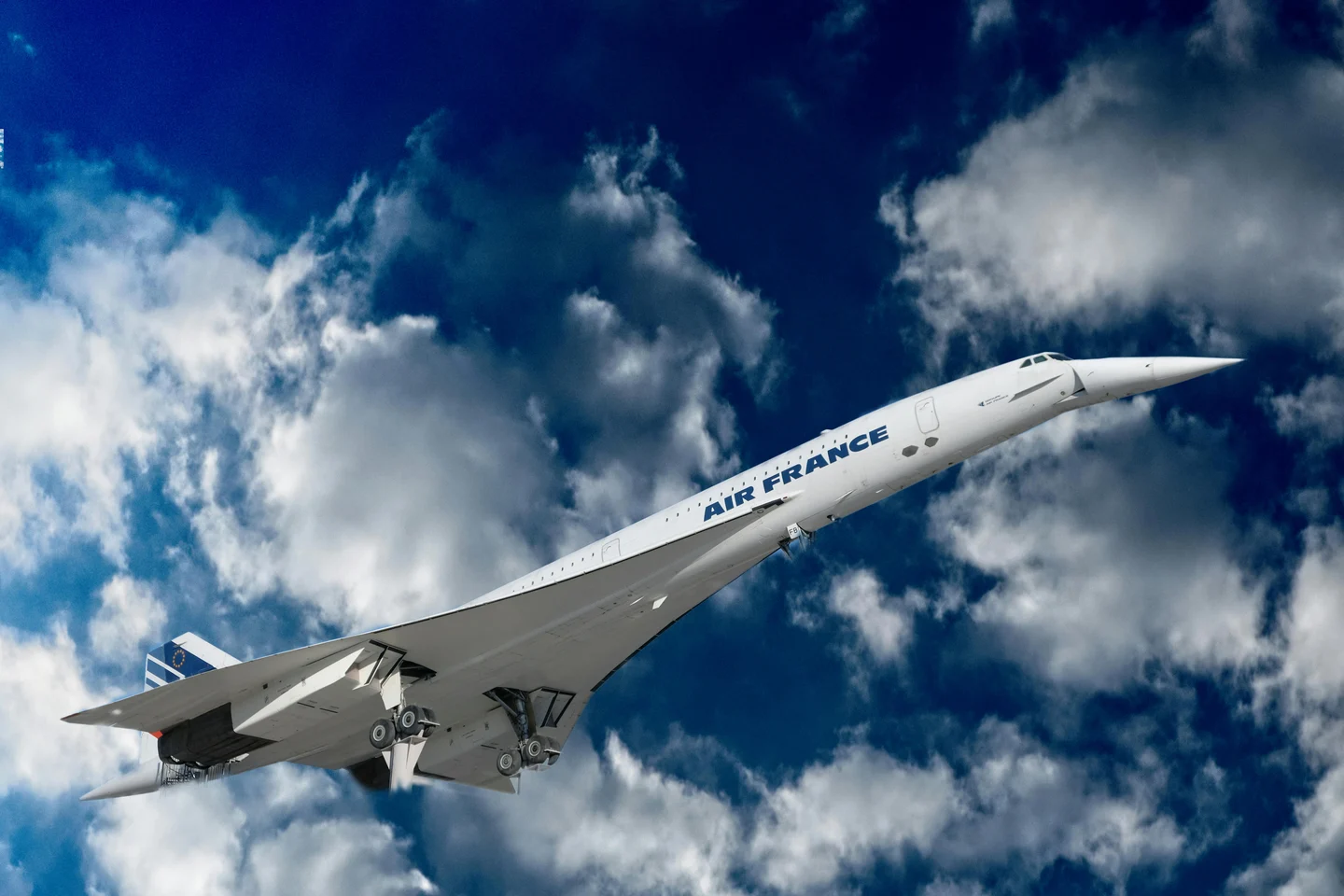
Cover image: Air France Concorde climbing through cloud cover, gear visible at take-off. Photo by Franz Herrmann via Pexels (Pexels license).
参考来源
- 1Wikipedia: Concorde
- 2Heritage Concorde: Airframe Materials
- 3Wikipedia: Rolls-Royce/Snecma Olympus 593
- 4Concorde SST: Powerplant
- 5Heritage Concorde: Olympus 593 Engines
- 6Heritage Concorde: Fuel Transfer
- 7Heritage Concorde: Fly by Wire
- 8Concorde SST: Flight Systems
- 9Heritage Concorde: Nose and Visor
- 10Wikipedia: Air France Flight 4590
- 11FAA: Concorde Lessons Learned
- 12AIAA: Let's Re-Engine the Concorde! RFP
- 13Wikipedia: Boom Overture
- 14Boom Supersonic: Year in Review 2025
- 15Wikipedia: LAPCAT
- 16Air France: 50th Anniversary Documentary
围绕这条内容继续补充观点或上下文。