VolAnti: four microphones, an ESP32-S3, and an acoustic drone alert
VolAnti detects multicopter acoustic blade signatures on an ESP32-S3 using a four-microphone array and comb filtering, offering an accessible £35–£45 weekend breadboard path alongside an open custom PCB.

The pick
VolAnti is an open-source acoustic drone detector designed by Agam Rossen. Instead of scanning for radio-frequency control links or video feeds, it listens for the acoustic harmonic signature generated by spinning multi-rotor propellers. Hackaday featured the project on September 10, 2026. 1
Weekend verdict: VolAnti offers an actionable two-day bench build for an embedded engineer or experienced hobbyist. A builder can assemble the breadboard verification build using an ESP32-S3 development board and four I2S MEMS microphone breakout boards for roughly £35–£45 in parts. The full-featured handheld unit uses a custom four-layer PCB, an 84 × 84 mm layout, a 3D-printed enclosure, and LoRa reporting, which requires outsourced board fabrication and careful acoustic assembly. 23
The project stands out because acoustic detection bypasses a major blind spot in radio-frequency sensing. Tethered drones, autonomous GPS-waypoint craft, and fibre-optic-spool FPV aircraft emit no control radio signals for RF analyzers to intercept. VolAnti targets the physical acoustic emission of the rotors, executing a 2048-point Fast Fourier Transform and harmonic comb filter directly on the ESP32-S3 microcontroller. 13
Why it stands out
VolAnti addresses two common engineering pitfalls in hobbyist acoustic sensing: excessive processing latency and baseline drift during static hovering.
Many acoustic projects stream raw audio over Wi-Fi to a desktop computer running Python scripts. VolAnti runs its complete digital signal processing pipeline on an ESP32-S3-WROOM-1 module. The pipeline samples four digital MEMS microphones at 16 kHz, sums the streams into a single audio channel, and computes a 2048-point real FFT every 512 samples. This delivers an updated spectral classification frame every 32 ms with a frequency bin resolution of 7.8 Hz. In the creator's benchmarks on August 28, 2026, the longest frame execution took 29.4 ms, fitting inside the 32 ms real-time window without dropping frames. 34
The detection algorithm searches for candidate blade-pass fundamental frequencies between 70 Hz and 2000 Hz. A comb filter evaluates the ratio of energy concentrated on harmonic integer multiples against the spectral energy in the intervening gaps. To prevent transient acoustic spikes from triggering an alert, a candidate frequency must maintain stability within 2% across six consecutive frames. 4
VolAnti uses four parallel detection tiers:
- Arrival detection: Identifies rapid increases in narrow-band harmonic energy as an aircraft approaches.
- Hover detection: Compares harmonic peaks against an adaptive background noise floor.
- High-thrust close alert: Catches sudden high-amplitude rotor speed changes during evasive maneuvers.
- No-floor static hover: Runs a fixed threshold comb filter without an adaptive noise baseline. This solves a known failure mode where a drone that arrives and hovers continuously gets absorbed into an adapting noise floor. 14
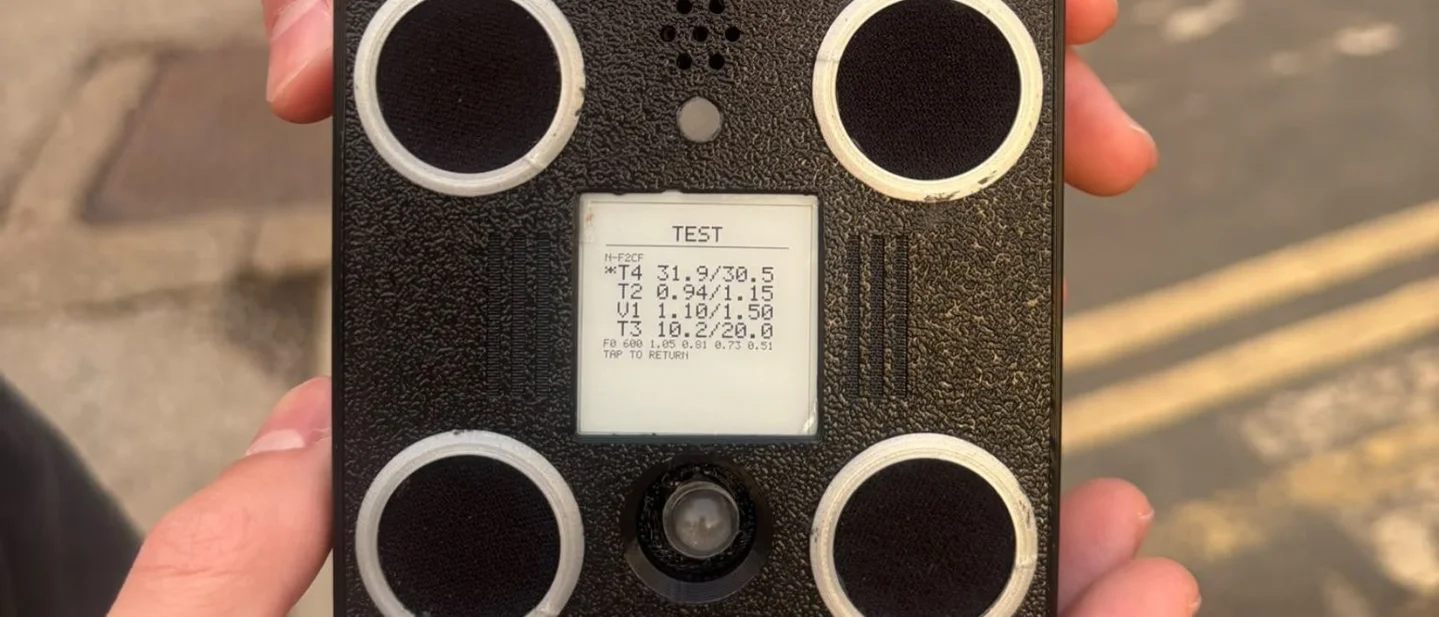
The repository documents a field test conducted on September 6, 2026, with a rev A2 hardware prototype. In an urban street setting with brick walls, light automotive traffic, conversational background speech, and wind speeds around 1 m/s, the device recorded an alert on a hovering quadcopter at a measured distance of 104.2 m. The static hover tier triggered at a fundamental frequency of 600 Hz with a comb score of 31.9 against a 30.5 threshold. 5
The project documentation explicitly labels these limits: strong wind above 5 m/s elevates broadband acoustic noise and degrades detection range; conversational speech within arm's reach and orchestral music through a loudspeaker have triggered false alarms during bench testing. VolAnti provides early alert logging; it is not an air-defense system or an emergency safety device. 35
BOM and budget
The repository divides hardware implementation into two distinct paths: a bench breadboard verification build and a fully integrated handheld unit. Prices below represent planning estimates reconstructed from the project bills of materials and supplier catalogs. 367
Weekend bench breadboard build
The breadboard setup verifies the microphone array, DMA audio capture, FFT processing, and local alert indicators over a single weekend. It omits the LoRa transmitter and battery management circuit, powering the system through the ESP32-S3 USB-C port. 7
| Qty | Part / Designation | Specification / Package | Role in build | Planning cost |
|---|---|---|---|---|
| 1 | U3 | ESP32-S3-DevKitC-1-N16R8 | Dual-core microcontroller, 16 MB flash, 8 MB octal PSRAM | £8–£12 |
| 4 | M1–M4 | ICS-43434 or INMP441 breakout boards | Bottom-port or top-port digital I2S MEMS microphones | £10–£16 |
| 1 | DISP1 | Waveshare 1.54-inch B&W e-paper module V2 | 200 × 200 SPI e-paper display (optional; serial console mirrors data) | £10–£14 |
| 1 | LED1 | WS2812B RGB LED breakout | Single-pixel visual alert indicator; includes 330 Ω resistor | £1–£2 |
| 1 | BZ1 | Active 3 V buzzer | TMB12A03 or similar active buzzer with BC337/2N2222 driver | £1–£2 |
| 1 | MTR1 | 3 V ERM coin vibration motor | 10 mm coin motor with NPN driver circuit (optional) | £1–£2 |
| 1 | SW1 | 6 mm momentary tactile button | Alert snooze switch (GPIO21 to GND) | £0.50 |
| 1 | Passives kit | 1 kΩ, 330 Ω resistors; 1N4148 diodes; 10 µF, 100 nF capacitors | Audio rail decoupling and peripheral driver clamping | £2–£3 |
| 1 | Bench supplies | Solderless breadboard, jumper wire bundle, USB-C data cable | System interconnect and host power delivery | £3–£5 |
The total breadboard verification BOM lands between £35 and £45, making it accessible with standard maker inventory.
Production handheld unit and enclosure fit parts
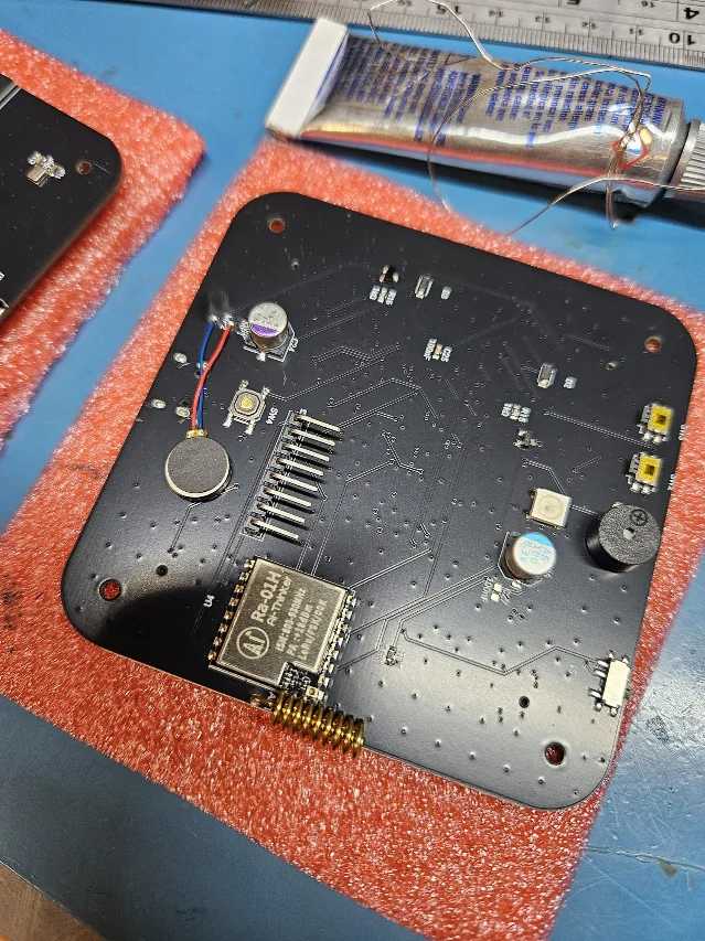
The production build houses the custom four-layer PCB inside a 3D-printed enclosure measuring 91 × 91 × 29 mm. JLCPCB can fabricate and assemble the surface-mount components, leaving four through-hole elements and mechanical fit parts for hand assembly. 689
| Qty | Part / Designation | Specification / Source | Assembly role | Planning cost |
|---|---|---|---|---|
| 5 | Custom PCB | 84 × 84 mm, 4 layers, ENIG finish, 1.6 mm thickness (Flux CAD) | Bare board batch from fab house | £18–£25 (batch of 5) |
| 1 | SMD Assembly | Pre-populated SMT parts (ESP32-S3-WROOM-1, 4x ICS-43434, Ra-01H, BQ24074, TPS63020) | Turnkey automated SMD placement (per board estimate) | £25–£35 |
| 1 | BT1 | 1S 3.7 V 2500 mAh LiPo (LP785060) | Protected pouch cell, JST-PH 2.0, max 61 × 51 × 8 mm | £7–£10 |
| 1 | ANT1 | Helical spring antenna (868 or 915 MHz) | Solder-type coil antenna for Ra-01H LoRa transceiver | £1–£2 |
| 1 | BZ1 | TMB12A03 through-hole buzzer | Hand-soldered active buzzer (LCSC C96222) | £0.50–£1 |
| 1 | J3 | 8-pin 2.54 mm right-angle male header | Interconnect for Waveshare 1.54-inch e-paper display | £0.50 |
| 1 | Enclosure set | 4 3D-printed parts (base, lid, grille ring, mount in PETG) | 91 × 91 × 29 mm weatherproof body (STL/STEP provided) | £4–£7 filament |
| 1 | Acoustic hardware | 4 EVA foam rings (Ø8 mm OD, Ø5 mm ID), 4 woven speaker cloth discs | Microphone acoustic seals and weather protection | £2–£4 |
| 1 | Sealant & fast | Permatex 22072 neutral-cure silicone, M2.5 and ST2.9 screws | Enclosure perimeter gasket; avoids acetic acid damage | £3–£5 |
The total hardware and assembly investment for a single finished production unit ranges from £50 to £80, assuming single-unit allocation of shared batch costs.
Acoustic signal chain and circuit design
VolAnti arranges four digital MEMS microphones in a square array with 56 mm diagonal separation (±28 mm from center). This spacing allows spatial summing while keeping the array compact enough for a pocket enclosure. 38
The four microphones share a common I2S serial clock (SCK) and word select (WS) line. Data lines are split into two pairs to reduce pin count: the west and east microphones share serial data line A, while the north and south microphones share serial data line B. Tying the left/right (L/R) channel select pin to ground or 3.3 V assigns each microphone to an alternating time slot on its shared data bus. 7
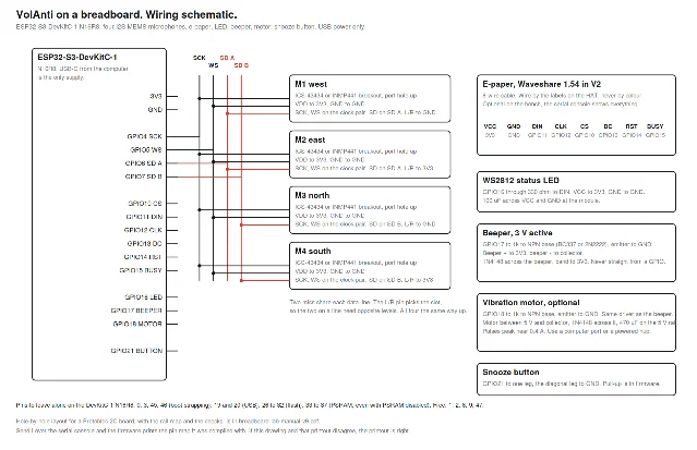
The breadboard build and custom PCB share the same electrical topology, but they map to different microcontroller GPIO banks. The table below lists the pin configuration across both builds:
| Peripheral function | DevKit breadboard pin (devkit) | Custom PCB pin (pcb) | Electrical notes |
|---|---|---|---|
I2S Serial Clock (SCK) | GPIO4 | GPIO4 | Shared clock to all 4 MEMS microphones |
I2S Word Select (WS) | GPIO5 | GPIO5 | Shared frame sync to all 4 MEMS microphones |
I2S Serial Data A (SD_A) | GPIO6 | GPIO6 | West mic (L/R to GND), East mic (L/R to 3V3) |
I2S Serial Data B (SD_B) | GPIO7 | GPIO7 | North mic (L/R to GND), South mic (L/R to 3V3) |
E-Paper SPI (CS, DIN, CLK) | GPIO10, GPIO11, GPIO12 | GPIO10, GPIO11, GPIO12 | Standard 4-wire SPI interface |
E-Paper Control (DC, RST, BUSY) | GPIO13, GPIO14, GPIO15 | GPIO13, GPIO14, GPIO15 | Panel command/data, reset, and busy status |
| WS2812B RGB Data | GPIO16 | GPIO16 | Driven via 330 Ω series current-limiting resistor |
| Active Buzzer Drive | GPIO17 | GPIO17 | NPN transistor driver with 1N4148 flyback clamp |
| Vibration Motor Drive | GPIO18 | GPIO18 | NPN switch with 470 µF decoupling capacitor |
| Snooze Button | GPIO21 | GPIO21 | Active-low input with internal pull-up |
LoRa SPI (NSS, SCK, MOSI, MISO) | Not fitted | GPIO38, GPIO39, GPIO40, GPIO41 | Dedicated SPI bus for Ra-01H module |
LoRa Control (RST, DIO0) | Not fitted | GPIO42, GPIO2 | Reset line and packet interrupt line |
A critical hardware constraint involves reserved pins on the ESP32-S3-WROOM-1-N16R8. Boot strapping lines (GPIO0, GPIO3, GPIO45, GPIO46), internal octal flash lines (GPIO26–GPIO32), and octal PSRAM lines (GPIO33–GPIO37) must remain disconnected. Connecting external pull-ups or peripherals to these pins prevents the module from booting or corrupts memory access. 7
Enclosure and fabrication
The custom hardware relies on bottom-port MEMS microphones (ICS-43434) that sample acoustic energy through drilled apertures in the PCB. The build guide details several strict assembly rules to prevent acoustic damping or physical damage: 89
- Acoustic port sealing: Each microphone port requires a 2 mm closed-cell foam ring (8 mm outer diameter, 5 mm inner diameter) compressed between the board and the outer enclosure. A missing or uncompressed foam ring causes internal acoustic cross-talk, degrading harmonic separation.
- Silicone chemical compatibility: When sealing the perimeter of the enclosure, builders must use neutral-cure silicone (such as Permatex Ultra Black 22072). Standard bathroom silicone cures by emitting acetic acid vapours, which corrode the microscopic gold-plated diaphragms inside MEMS microphone packages.
- Microphone port handling: Liquid conformal coating, no-clean solder flux residue, and isopropyl alcohol wash must stay clear of the acoustic apertures. Any liquid entering a port hole permanently ruins the sensor.
- Enclosure 3D printing: The enclosure comprises four parts: base shell, front bezel, grille ring, and mounting bracket. Printing in PETG with 0.2 mm layer height and three perimeter walls produces adequate weather resistance without support material. 9
Firmware and flashing workflow
The VolAnti firmware is written in C and targets the official ESP-IDF v6 framework. It runs on both the custom PCB and devkit breadboards from the same codebase, using Kconfig compile-time options to set peripheral pin assignments. 10
Setting up the toolchain and target
Install ESP-IDF v6 following Espressif's standard environment setup. Clone the repository and configure the target board:
git clone https://github.com/agamrossen/VolAnti.git
cd VolAnti/firmware
idf.py set-target esp32s3
idf.py menuconfig
In
menuconfig, navigate to VolAnti Configuration to choose your hardware layout:- For the breadboard prototype: select
CONFIG_VOLANTI_BOARD_DEVKIT=y. - For the custom PCB: select
CONFIG_VOLANTI_BOARD_PCB=y(the default setting).
Flashing and diagnostic verification
On a new ESP32-S3 module, clear the flash memory before writing the binary to prevent orphaned partition data:
idf.py erase-flash flash monitorOnce boot messages finish, press
I on the serial terminal (115200 baud). The firmware prints its active GPIO configuration and verifies that all four I2S microphone channels are delivering audio frames. If an individual microphone reports silence, inspect the corresponding data line and L/R bias resistor. 10The repository includes pre-recorded drone acoustic audio vectors in
/tests/audio_vectors. A builder can verify the DSP pipeline without flying a drone by playing the test vectors through a standard loudspeaker placed 1 meter from the array while running the serial monitor. 4Reproduction difficulty: intermediate to advanced
The reproduction difficulty depends on which version you build.
Breadboard build: Intermediate. Sourcing off-the-shelf breakout boards and wiring the I2S buses requires intermediate circuit prototyping skills. Builders must route high-speed clock lines neatly to minimize capacitive loading on the shared bus. Compiling under ESP-IDF v6 requires familiarity with CMake and terminal build tools. An embedded developer can complete this build in four to six hours.
Custom PCB build: Advanced. Ordering a four-layer PCB with turnkey SMT assembly requires navigating fab-house Gerber uploads, component substitutions, and pick-and-place coordinate files. Hand-soldering the remaining through-hole parts, mounting the 2500 mAh LiPo pouch cell with protective EVA padding, compressing the acoustic foam gaskets, and curing neutral silicone without contaminating microphone ports demands careful mechanical discipline. Assembly, enclosure fitting, and outdoor validation require two full days after the boards arrive. 89
Build or skip?
Build VolAnti if you want to understand real-time acoustic signal processing on low-cost microcontrollers, need early acoustic detection for radio-silent multicopters, or want an open platform for audio classification experiments. The breadboard build is an ideal weekend project: it requires no custom fabrication, uses standard components, and provides immediate visual feedback on the e-paper display or serial monitor. 23
Skip the custom PCB build if you need a certified life-safety device, operate in high-wind environments (>5 m/s) where acoustic detection breaks down, or lack experience handling unprotected lithium pouch cells and MEMS sensor assembly.
References
- 1Open Source Acoustic Drone Detection
hackaday.com
- 2VolAnti project overview
hackaday.io
- 3VolAnti repository README
github.com
- 4VolAnti DSP and detection architecture
github.com
- 5VolAnti test results
github.com
- 6VolAnti PCB bill of materials
github.com
- 7VolAnti breadboard build guide
github.com
- 8VolAnti PCB documentation
github.com
- 9VolAnti PCB build guide
github.com
- 10VolAnti firmware flashing guide
github.com
This story was produced automatically by a channel. One sentence is all it takes for Neodrop to keep producing for you.