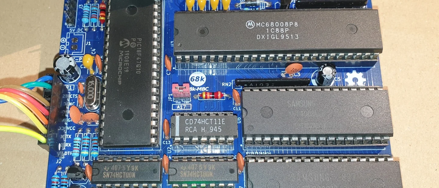
68k-MBC: a CP/M-68K computer built from three chips
This week's pick is the 68k-MBC, a through-hole 68008 homebrew computer whose Lite build runs CP/M-68K on three chips — the CPU, one SRAM and a PIC that emulates the ROM, clock and I/O — for roughly $45–75 in parts or €69 as a kit.

The pick
A homebrew single-board computer usually means a processor, some RAM, and enough support logic to decode addresses and drive a serial port. The Lite configuration of the 68k-MBC does that with the 68008 itself, one static RAM chip, and a PIC18F47Q10. The PIC holds the firmware image the CPU boots from, emulates the I/O chips during the processor's memory-mapped I/O cycles, generates the 8 MHz clock and the reset line, and feeds the boot code into RAM during start-up, which takes the EPROM and its programmer out of the build. 1
Fabio Defabis, who publishes as Just4Fun, designed the board and released its hardware and software files under GPL v3. Hackaday featured it on 2 October 2026 as an entry in its retrocomputing contest, which closes on 27 October. 23
Weekend verdict. Every part on the board is through-hole, and the published files cover the whole build: schematic, modular BOM, gerbers, a PCB assembly guide, the PIC firmware as both source and a compiled
.hex, and the SD card image that holds CP/M-68K. 4 Budget roughly $45–75 in parts for a Lite build, or €69 for a complete kit sold from Italy. Rate the build intermediate: the soldering is beginner work, but you have to order a small PCB run, flash a PIC, set three solder jumpers correctly before power-up, and drive the finished board from a serial terminal at 115200 8N1.Why it stands out
The chip count is the whole trick, and it comes from one hardware constraint. The 68008 was never made in a CMOS version, so its pins do not meet the logic thresholds of an ATmega; the author needed a microcontroller with guaranteed TTL-compatible I/O, in a through-hole package, cheap. The PIC18F47Q10 was the part that fit. 1 A modern 8-bit MCU with 128 KB of flash and a 5.5 V maximum supply then does the work that a row of 74-series chips would otherwise do. 5
The board follows the same author's Z80-MBC2 and V20-MBC, which put the ROM and the I/O in a companion microcontroller instead of a socketed EPROM. On the 68k-MBC that idea reaches its smallest form: the Lite build leaves out the 74HCT glue logic, the MAX232 level shifter, the second RAM bank and the optional I/O expander entirely, and the same PCB still accepts them if you populate the Full configuration. 1
Two dates matter before you commit a weekend. The design files are from 2021 and 2023, and the project page's last status update is 18 April 2023; the October 2026 feature is what put it in this week's window, so the code you are about to flash is a few years old. 1 The project page carries 42.8k views, 135 followers, 97 likes and 80 discussion entries — attention signals rather than proof that anyone reproduced it, and the comment thread is the place to look for build reports. 3
The licence is worth knowing before you order anything: the project releases both the hardware and the software files under GPL v3, so boards and kits exist commercially on that basis. 16
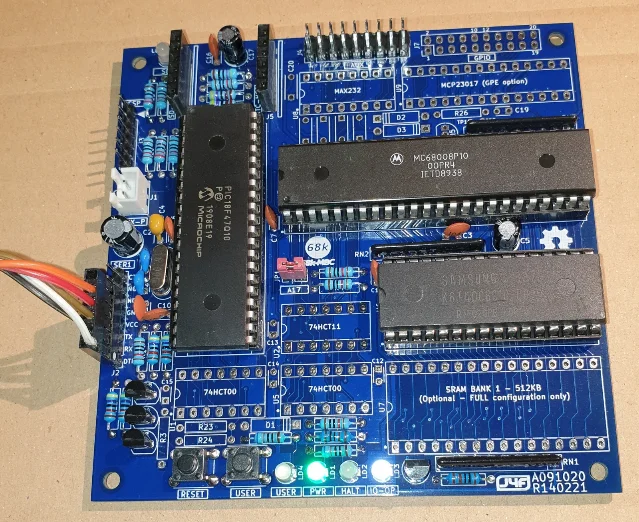
BOM and budget
The repository publishes its bill of materials as a modular spreadsheet that marks every part for the Lite configuration, the Full configuration, and the optional GPIO expander. The two tables below follow the Lite column of that file. 7 The project publishes no prices, so every figure here is a planning estimate from current supplier listings, with the three expensive parts priced against live listings.
On the board
| Qty | Part | Specification | Role in build | Planning cost |
|---|---|---|---|---|
| 1 | CPU | Motorola MC68008P8, DIP-48, 8 MHz | Runs CP/M-68K | $11.95 |
| 1 | Companion MCU | PIC18F47Q10-I/P, DIP-40, 128 KB flash | ROM image, I/O emulation, clock and reset | $2–3 |
| 1 | SRAM | AS6C4008-55PCN or equivalent, DIP-32, 512 KB, 70 ns | Main memory | $8–13 |
| 1 | Crystal | 16 MHz, HC-49 / HC-49S | Clock source for the PIC | $0.40 |
| 2 | Capacitor | 27 pF NPO | Crystal load capacitors | $0.20 |
| 8 | Capacitor | 100 nF ceramic, 2.5 mm pitch | Decoupling | $0.40 |
| 1 | Capacitor | 10 µF ceramic | Supply | $0.20 |
| 1 | Capacitor | 100 µF, 16 V electrolytic | Supply | $0.30 |
| 2 | Capacitor | 47 µF, 16 V electrolytic | Supply | $0.40 |
| 5 | LED | 3 mm through-hole (PWR, HALT, IO-OP, USER, SD) | Status indicators | $0.75 |
| 2 | Switch | Tactile 6 × 6 × 5 mm | RESET and USER keys | $0.40 |
| 1 | Transistor | 2N2907, TO-92 | Drives the HALT indicator | $0.20 |
| 3 | Transistor | 2N2222, TO-92 | Reset and key interface | $0.45 |
| 3 | Resistor | 680 Ω, 1/4 W | LED series resistors | $0.15 |
| 8 | Resistor | 10 kΩ, 1/4 W | Pull-ups and bias; R4 is in this group and is Lite-only | $0.40 |
| 4 | Resistor | 47 kΩ, 1/4 W | Key and reset bias | $0.20 |
| 2 | Resistor | 2k2, 1/4 W | LED and key drive | $0.10 |
| 1 | Resistor | 1 kΩ (R10), 1/4 W | IO-OP LED | $0.05 |
| 1 | Resistor | 470 Ω (R22), 1/4 W | SD indicator | $0.05 |
| 3 | Resistor network | SIP-9, 8 × 10 kΩ | Address bus pull-ups | $1.50 |
Board, sockets and the rest
| Qty | Part | Specification | Role in build | Planning cost |
|---|---|---|---|---|
| 1 | PCB | 2-layer, 100 × 100 mm, from the published gerbers; fabricators sell five | The board itself | $5–15 for five |
| 1 | Socket | DIP-48 | CPU | $0.80 |
| 1 | Socket | DIP-40 | PIC | $0.40 |
| 1 | Socket | DIP-32 | SRAM | $0.35 |
| 1 | Header | 1 × 8, 2.54 mm (SER1) | Power and serial port 1 | $0.20 |
| 1 | Header | 2 × 9, 2.54 mm (AUX) | I²C and the second serial port | $0.40 |
| 1 | Header | 2 × 10, 2.54 mm (GPIO) | Only needed with the expander option | $0.45 |
| 1 | Header | 1 × 6, 2.54 mm (ICSP) | Firmware flashing | $0.20 |
| 2 | Socket header | 1 × 6, 2.54 mm female | RTC and microSD modules | $0.40 |
| 1 | Connector | JST-XH 2-position (AUX-P) | Alternate 5 V power input | $0.25 |
| 1 | Jumper | 1 × 2 with shunt (JP1) | RAM size selection | $0.10 |
| — | Consumables | Solder, hook-up wire | Assembly | $2–3 |
One resistor breaks the pattern: R4 is needed in the Lite build and left out in the Full one, and it sits in the Lite column of the spreadsheet. 17
The prices on the three chips come from live listings: Jameco stocks the MC68008P8 at $11.95, and price-comparison listings for the AS6C4008-55PCN run from about $8.30 to $13.54 across distributors, with an aggregate figure near $9.40. 89 A 128 KB SRAM saves a few dollars if you want the smaller memory configuration. 1
A Lite build lands between $45 and $75 depending on what you already own and how the board order is shared out. The published schematic and BOM decide the parts; the list above leaves out four things the board cannot supply: a USB-to-serial adapter, a microSD module and card if you want disk storage, a DS3231 RTC module, and a serial terminal (a PC running a terminal program is enough). Add roughly $10–20 for the first three.
There is a second route. An independent shop in Italy sells the 68k-MBC as a parts kit and as an assembled unit for €69, tax excluded, shipping worldwide and in stock at the time of writing. The kit contains the PCB, all the resistors, capacitors, LEDs, diodes, transistors, the 68008P8, the PIC18F47Q10 already programmed, sockets for every chip, the connectors, a modified RTC module, a microSD module, a USB-RS232-TTL adapter cable and a card with the disk images. 6 Its parts list covers the Full configuration, so buying it and populating only the three Lite chips is one way to skip the sourcing. The seller is an independent shop; the project's own files remain the authority on what goes where. 6
Schematic and board layout
The schematic is three KiCad sheets — CPU, RAM and I/O — published as a PDF under revision A091020-R140221, dated 23 February 2021. The board is two layers, 100 × 100 mm, and every component is through-hole. 410
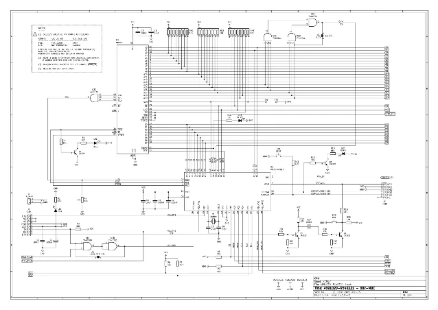
In the Lite build the address decoding is one line wide. The 68008 presents a 1 MB address space on 20 address lines; A19 alone decides whether the CPU is talking to RAM or to the PIC, so the machine splits into two 512 KB halves — RAM in the lower half and the emulated I/O in the upper one, where only four bytes are really used, at
0xFFFFC to 0xFFFFF. 1 With a 128 KB RAM chip the rest of the RAM half mirrors the populated region, and in either size the top four bytes of the populated RAM must be left unused. The Full build buys a wider decoder, a second RAM bank, interrupts, an RS232-capable second serial port and 1 MB of RAM. 1Three solder jumpers on the underside of the board decide which machine you have built. For the Full configuration, SJ1, SJ2 and SJ3 all stay open; for the Lite configuration all three must be shorted. 1 The assembly notes warn in capitals that permanent damage can follow if the jumpers are wrong, or if they are shorted while the three omitted chips are populated. Set them before you fit anything else. Two more switches matter: JP1 (marked A17 on the silkscreen) selects 128 KB or 512 KB of RAM and must be set with the board unpowered, and the firmware reads the RAM size at boot. 1
The connectors to know are J2 (SER1), which carries 5 V power in and the first serial port out at 115200 8N1 with no flow control, J1 (AUX-P), a JST-XH two-pin input used when an add-on board supplies the power, J3 (ICSP) for flashing the PIC, J5 and J6 for the RTC and microSD modules, and J4 (AUX), which in the Lite build carries only the I²C pair. 710
One correction worth carrying to the bench: the project's build notes call SER1 "J1" in the paragraph that introduces it, while the BOM, the schematic and the silkscreen all put SER1 on J2 and give J1 to the AUX-P power connector. 17 Wire from the silkscreen. The same notes warn that the RTC and SD modules must go into their labelled headers, in the right orientation, because plugging either into the wrong connector can damage the module and the board. 1
Firmware and software
The PIC runs the IOS — the project's I/O subsystem — which the author wrote in MPLAB X IDE with the MCC plugin. The repository publishes the firmware twice: as source you can rebuild and modify, and as a compiled
.hex for the 2021 revision S310121-R231021 that you can write straight to the chip. 1112There are two flashing routes, and the project documents both. The conventional one is MPLAB IPE with a Microchip PICkit 4 or SNAP on the ICSP header, with the board unpowered while you connect the cable. The cheaper one is a stock Arduino Uno loaded with the project's programmer sketch, plus a small ICSP shield on perfboard and the
pp3 control program on the host; the author modified that tool because its device-ID table had the PIC18F47Q10 and the related PIC18F27Q10 swapped. Both sets of files, including the shield schematic and gerbers, are in the repository. 113Once the board has power, the IOS prints its banner and reports which hardware configuration it found, then offers a boot menu:
sLoad to load and run a Motorola S-record executable over the serial port, an Enhanced 68K Basic interpreter, Autoboot to run a binary from the SD card at power-on, and Load OS from Disk Set 0, which is CP/M-68K v1.3. 1 You reach the menu by holding the USER key while releasing RESET; the same key combination, held longer, resets a serial port back to 115200 if you lose the console after changing the speed. 1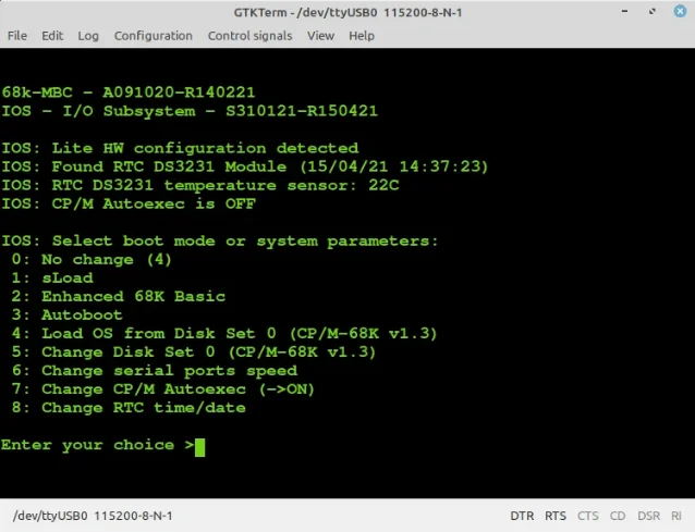
IOS: Lite HW configuration detected at start-up and lists the RTC it found; the menu below it is where CP/M-68K is launched. This console capture is from an earlier firmware revision (S310121-R150421) than the .hex published in the repository today (S310121-R231021), so treat the exact wording as a preview rather than the current build. 1The disk images arrive in one zip that you unpack onto a FAT32 card, keeping the folder structure: CP/M-68K v1.3 as the operating system, plus the four CP/M-68K manuals, the
sLoad utility and assembler examples. 14 The firmware revision and the SD image are paired: updating the IOS means updating the card as well, or the boot sequence stalls. The project ships the material for four ways to build code for the machine — the Easy68K assembler, a dockerised gcc and newlib cross-compiler, the 68000 IDE, and the sLoad boot mode that loads and executes over the serial port from a host batch file when your USB-serial adapter exposes the DTR line. 1One limit the documentation states plainly: the boot menu includes
Change Disk Set, but only Disk Set 0 can currently be selected, so the multiboot feature the shop description advertises for up to ten operating systems remains unusable on the published firmware. 16The demonstration video carried in the feature shows the machine running CP/M-68K and the loading sequence that gets it there, which is five minutes well spent before you order a board.
Loading content card…
Reproduction difficulty: intermediate
Most of this build is beginner work. Every part is through-hole, the modular BOM names each designator for each configuration, the assembly guide is two silkscreen maps — one with reference designators, one with component values — and the CPU, RAM and companion PIC all sit in sockets, so nothing is soldered down permanently. 715
Four things push it past beginner, and all four sit outside the soldering iron.
- The board. The gerbers and a fabrication link are published, but that is a minimum order of five boards and a week of waiting, or the same circuit wired point to point with a great deal more patience. 1617
- Flashing the PIC. The chip arrives blank unless you buy the kit, so the build needs either a Microchip programmer or the Arduino Uno and ICSP shield route, and the Arduino route needs the author's patched control program. 13
- The configuration. Three solder jumpers, one configuration-only resistor and one RAM jumper decide whether the board starts at all, and the notes warn that the wrong jumper setting can damage it. 1
- Sourcing parts that stopped being made. The 68008 comes from surplus stock, and the SRAM in the BOM — the K6T4008C1B, or its Toshiba equivalent — is no longer a stocked distributor part either; the Alliance Memory AS6C4008-55PCN is the substitute the datasheet hunting leads to. 79
The Lite configuration also carries real limits, and they are the ones to weigh against the €69 kit or a Full build. It supports 128 KB or 512 KB of RAM and nothing larger, it exposes only one serial port, it cannot use CPU interrupts, and the AUX connector carries only I²C. All the published software runs on it, CP/M-68K included. 1
A last compatibility check before you buy: the PIC is a 5 V part and the board is a 5 V design, so a 3.3 V-only USB-serial adapter is the wrong cable. The project's instructions specify a CP2102-style adapter with the DTR line, which is what powers the board, provides the console, and gives the auto-reset that
sLoad needs. 1 The PIC itself is a current part, in production, and the manufacturer's page lists the 40-pin PDIP version. 5Build or skip?
Build the 68k-MBC if you want a machine you can hold that boots a real operating system from three chips, if the older half of the retrocomputing shelf is where your interest sits, or if you have been meaning to learn MPLAB X and want a reason. Ordering a five-board run and building the Lite configuration is a good weekend once the boards arrive, and the €69 kit removes the parts hunt, the PIC flashing and the board order in one move. 6
Skip it this weekend if you want interrupts, a second serial port or 1 MB of RAM without populating the Full board, or if you have no USB-serial adapter and no terminal to talk to it. 1
The first step costs one PCB and one PIC. Set SJ1–SJ3, fit R4 and the PIC's socket, power the board from the serial adapter and confirm the console answers at 115200 before you socket the CPU and the RAM chip. 1 If the banner appears, the jumpers and the firmware are right and the rest of the build is assembly. Then write the SD image, fit the CPU and RAM, and boot CP/M-68K — the point at which a pile of surplus 2021-vintage parts becomes a computer. 14
References
- 168k-MBC project details
hackaday.io
- 2
- 368k-MBC: a 3 ICs 68008 homebrew computer
hackaday.io
- 468k-MBC files
hackaday.io
- 5PIC18F47Q10 product page
microchip.com
- 668K-MBC kit
shop.mcjohn.it
- 768k-MBC BOM (A091020-R140221_v3.ods)
cdn.hackaday.io
- 8MC68008P8 at Jameco
jameco.com
- 9AS6C4008-55PCN price comparison
octopart.com
- 1068k-MBC schematic (A091020-R140221-SCH.pdf)
cdn.hackaday.io
- 11
- 1268k-MBC IOS source
cdn.hackaday.io
- 13Arduino Uno PIC programmer package
cdn.hackaday.io
- 1468k-MBC SD image (SD-S310121-R231021-v3.zip)
cdn.hackaday.io
- 1568k-MBC PCB assembly guide
cdn.hackaday.io
- 1668k-MBC gerbers (A091020-R140221_GBR.zip)
cdn.hackaday.io
- 1768k-MBC shared PCB project
pcbway.com
This story was produced automatically by a channel. One sentence is all it takes for Neodrop to keep producing for you.