Two coils and an ESP32-S3 put internet radio back on longwave
This week's pick is a printed box that plays internet radio into an ESP32-S3 and re-broadcasts it as a longwave AM carrier, two independent transmitters on one board, for roughly $20–35 and a beginner's evening — provided a radio in the house still covers longwave.

The pick
An ESP32-S3 streams an internet radio station over Wi-Fi and re-broadcasts it as an amplitude-modulated longwave carrier out of a single GPIO pin, so an ordinary radio across the room picks it up. One board carries two of these transmitters, each with its own station, carrier frequency, modulation depth and output pin. 1
Gareth Davies designed it and publishes the firmware, the case geometry, a flashable binary and five manuals under GPL-3.0. The repository went up on 21 September 2026 and last saw a push on 7 October; Hackaday featured the project on 7 October 2026. 23
Weekend verdict. Parts come to roughly $20–35 — a development board, a reel of enamelled wire, heat-set inserts, screws and a USB-C cable — plus about 40 g of filament. An evening covers the printing, the winding and the flashing once the case is off the bed, and the firmware arrives as one merged binary that needs no compiler. Rate the build beginner, with one caveat: the finished box radiates inside a licensed broadcast band on an unfiltered square-wave carrier. Read "Before you switch it on" before you order anything. 45
Why it stands out
Most DIY AM transmitters in this corner of the hobby generate one carrier. This one makes two from a single board: separate decoders, separate DSP chains, separate carrier frequencies and separate loops, with only the ground shared. Tune one receiver to 200 kHz and another to 250 kHz, and the two play different stations at the same time. The author measured each 48 kHz chain at 41.8 decoded frames per second with the modulator keeping up, on the same board you would buy. 6
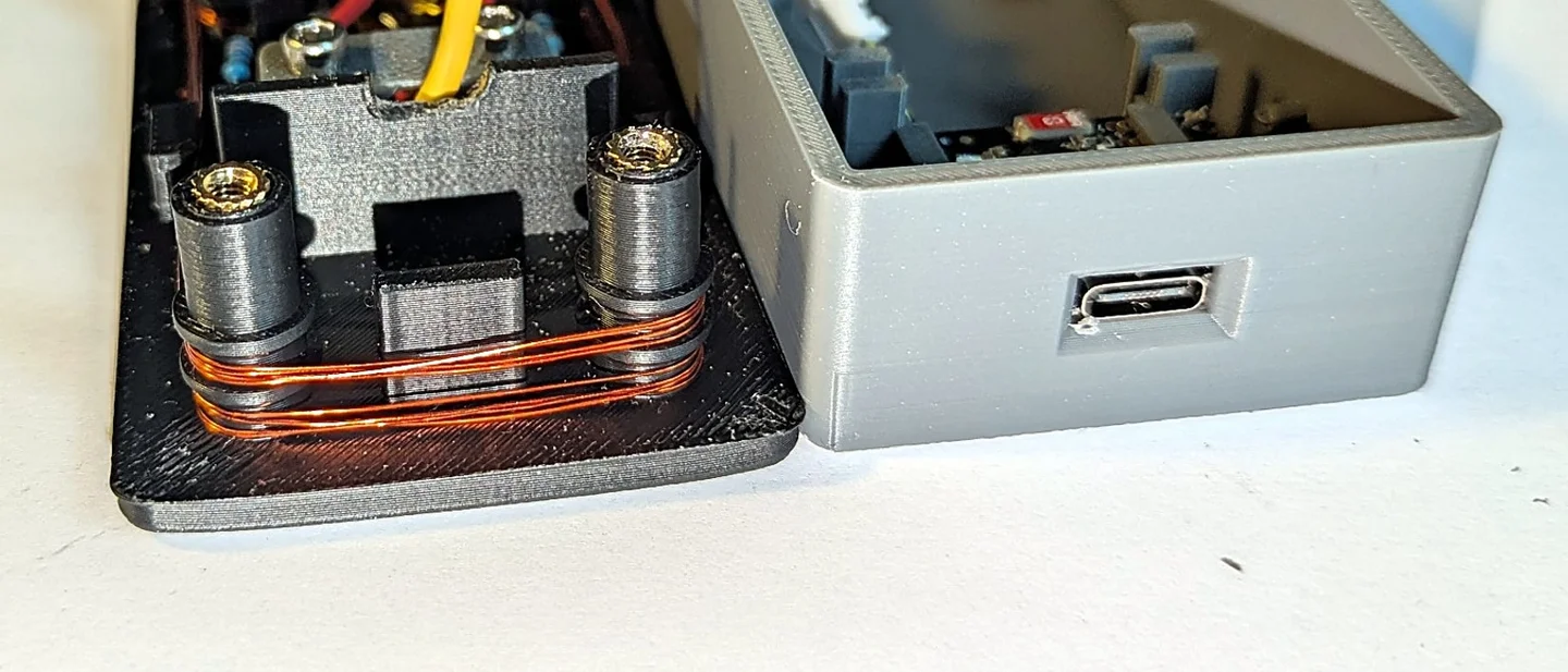
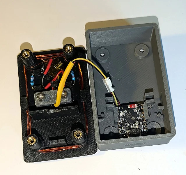
The enclosure is the second idea, and the better one. Every part of the antenna is printed. The lid's four corner pillars are the winding former, the lid is the radiator, and those same four pillars take the screws that close the box. A printed enclosure that doubles as the antenna is a rare thing to be able to make at home, and its geometry ships as both STEP and STL. 2
The third is the modulation itself, which the firmware solves at the level of the physics. That argument is worth reading even if you never build one, and it is set out below. 6
Attention signals, kept separate from evidence: the repository carried 19 stars and no forks when this was written, and the only reproduction account in it is the author's own. 2 He also states plainly that the public repository is a mirror of a private working one, so the design documents and issue registers it mentions live outside the public tree. 7
BOM and budget
The project publishes no prices, so treat every figure here as a planning estimate built from live retail listings and commodity parts. Quantities and specifications come from the build manual's own parts list. 4
| Qty | Part | Specification | Role in build | Planning cost |
|---|---|---|---|---|
| 1 | Development board | Waveshare ESP32-S3-Zero, ESP32-S3FH4R2, 4 MB flash, 2 MB PSRAM, 23.5 × 18 mm | Runs both transmitters; the case is cut to its footprint | $7 (£5.30) |
| 2 | Resistor | 220 Ω, 1/4 W, carbon or metal film | Series element from each GPIO pin into its loop | $0.20 |
| 1 | Wire | 0.3 mm enamelled copper, about 1.5 m — sold as magnet or transformer wire | Both five-turn windings | $2–4 |
| 4 | Heat-set insert | M3 brass, about 4 mm outside diameter, 5–6 mm long | Metal threads in the lid's four pillars | $2–3 |
| 4 | Screw | M3 countersunk, 8–10 mm | Close the base onto the lid | $2 |
| 2 | Screw | M3 self-tapping, short | Cable clamp, needed only if a cable leaves the box | optional |
| 1 | Cable | USB-C data cable, not charge-only | Power and the serial console | $3–6 |
| 1 | Filament | PLA, about 40 g | Base, lid and clamp | $1–2 |
| 1 | AM receiver | Must cover longwave for the default 200 kHz carrier | Proves the build works | already owned |
The board is the one line worth anchoring to a live price: The Pi Hut lists the base ESP32-S3-Zero at £5.30 including VAT, about $7, and Waveshare's product page sets out the four variants of the board. 89 The 8 MB flash with 8 MB PSRAM version, the -N8R8, also runs the firmware, and the author tested both memory layouts. 6
Everything else on the list is commodity hardware that arrives in packs of ten, so the totals above are rough. A build lands between $20 and $35 depending on what is already in the parts bin. 4
Three more things belong alongside the list. You need an FDM printer and about 40 g of PLA, or a printing service: for services that charge a minimum per part, the repository includes a sprue file with all three on one runner. You need a soldering iron, plus a spare tip you are willing to use at about 200 °C for the heat-set inserts. And you need a radio that covers longwave; the reason that matters is set out under reproduction difficulty. 4
What is wired to what
One transmitter is a GPIO pin, a 220 Ω resistor, a five-turn loop and a ground return. There are two of them, and they share only the ground. 4
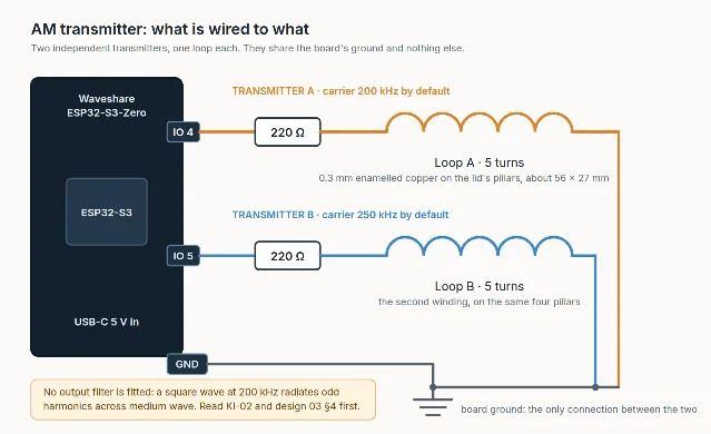
The loop is wound on the lid itself. The four corner pillars are the former, each with two channels separated by a flange, so one lid carries two independent windings of five turns of 0.3 mm enamelled copper. Five turns around that former enclose about 56 × 27 mm, or roughly 15 cm², which is the area the author tested and heard on a receiver. 410
Two details decide whether it works. Scrape the enamel off about 8 mm of each winding tail before soldering, because enamelled wire looks like bare copper and an unscraped joint looks perfect and conducts nothing. And keep the two windings apart, which is what the flange between the channels is for: two carriers sharing one output network intermodulate. 46
The RF section is one resistor and one loop. The square wave on the pin is the carrier and the coil is the radiator, and the only thing between them is a 220 Ω resistor. That is why the harmonics matter, and "Before you switch it on" deals with them. 7
The case prints as three parts — base, lid and clamp — in PLA at 0.2 mm layers, 25% infill and no supports, in the orientation supplied. Load the base and the lid as separate objects: they share an origin and a footprint, and a slicer told to treat them as one object prints them inside each other. 4
Firmware and software
The firmware is an ESP-IDF v5.3 project, shipped as source and as a merged binary. Each chain is a full audio path: HTTP MP3 into a 64 kB ring buffer in PSRAM, decoding by libhelix, a mono downmix, a DC block, a sixth-order low-pass at 4.5 kHz, a resample to 20 kHz, a loudness AGC, a peak limiter, a lock-free FIFO, and a 20 kHz interrupt that writes the LEDC duty register. The two decoders and the interrupt share one core, and everything the interrupt touches stays in internal RAM, because PSRAM is reached over SPI. 6
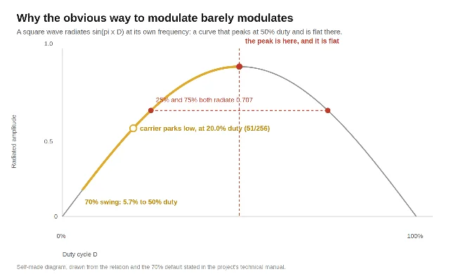
The interrupt is where the interesting decision sits. A square wave radiates at its own frequency in proportion to sin(πD), where D is the duty cycle, and that curve peaks at 50% duty — the one point on it with zero slope. Modulating the duty around 50%, which is the obvious reading of the brief, therefore changes almost nothing: 25% and 75% both radiate 0.707, as the figure below shows. The firmware puts the peak of the modulation at 50% duty instead, parks the unmodulated carrier at 1/(1+m) of it, and inverts the sine into a 512-entry table. For the default depth of 0.70 the quiescent duty is asin(1/1.70)/π = 0.2002, or 51 of 256 register steps, and the boot log prints that number so you can confirm the table was built. 6
Flashing is one command. Install
esptool, then write the merged image at offset zero, using the board's own USB-C socket rather than a separate adapter:pip install esptool
python -m esptool --chip esp32s3 -p COM5 write_flash 0x0 amtx-v1.0-merged.binA brand-new ESP32-S3 can drop off the USB bus while you try; hold the BOOT button as you plug it in to force the ROM's download mode. 4 Two desktop tools in the repository do the same job with a graphical interface, and the installation manual covers building the firmware from source with ESP-IDF. 11
On first boot with no saved network, the board raises its own access point called
AMTX-Setup and serves a setup page at 192.168.4.1. Pick your network from its scan list rather than typing the name, because the radio is 2.4 GHz only. After it joins, the control page lives at http://amtx.local, and out of the box it plays Radio Swiss Jazz on transmitter A at 200 kHz and the BBC World Service on B at 250 kHz. 4You drive all of it from that page or from a serial console on the board's native USB port. The console reaches every function the page does, which is what keeps a board with broken Wi-Fi reachable. Anyone on your network can open that page, and it can also be switched off — after which only the console brings it back. 5
Where the firmware stops is worth knowing before you plan around it. The carrier runs from 60 to 300 kHz, and 312.5 kHz is a hard ceiling because the hardware divides an 80 MHz clock into 256 duty steps; ask for 800 kHz and the transmitter refuses and keeps what it had. Modulation depth runs 5 to 90%, with 70% the default and anything above 75% pinching the trough into distortion on the cheap envelope detector inside an AM radio. Audio low-pass runs 500 to 9500 Hz, and the default holds the transmission inside a 9 kHz channel. 5
The decoder handles MP3 only, over plain HTTP only. The station list holds 20 entries and the community directory search returns 10 results, though the source of that cap — internal RAM during a secure connection — is one the author notes could now be raised. 5
Reproduction difficulty: beginner
This is a beginner build with an evening's worth of work in it. The build asks for a printer, a soldering iron and a USB-C cable; everything else is software. Flashing is one Python command, the soldering is about ten joints, and the build manual assumes only that you can solder a joint and use a screwdriver. 4
Four things carry the risk, and none of them is the electronics.
- The printer. Three parts, printed in the orientations supplied, all with their overhangs flared so the slicer needs no supports. Without a printer, the sprue file puts all three on one runner for a service that charges per part. 4
- The enamel. A winding that is not electrically connected is the most common fault, and it looks exactly like one that is. 4
- The board footprint. Other ESP32-S3 boards run the firmware; the case itself is cut for the footprint of the 23.5 × 18 mm Waveshare ESP32-S3-Zero. 412
- The receiver. This is the one that can end the build before it starts. The build manual's parts list suggests retuning the transmitter to medium wave if your radio has no longwave, while the user manual sets 312.5 kHz as a hard ceiling on the carrier, and the medium-wave band begins above 500 kHz. For a radio that covers medium wave and FM alone, this transmitter as published is inaudible. 45
The project is unusually clear about the line between built and proven, and one pair of statements in it is worth reading together. The repository's summary reports two stations playing at once and heard on an AM receiver, each decoder sustaining full rate. The technical manual states that nothing has been measured off-air, that no receiver, scope or spectrum analyser has been on the project at any point, and that harmonic content, radiated field strength and modulation depth are all unobserved. Take the audible result as the author's report, and treat the RF numbers as absent. 67
Two smaller gaps are declared in the same spirit: the published case revision fixes what the previous print got wrong and has not itself been printed, and the factory-reset gesture — holding the B button for five seconds — has been built but never pressed. 7
Before you switch it on
The carrier lands inside a licensed broadcast band. The default 200 kHz sits in the longwave broadcast band, 2 kHz from BBC Radio 4 on 198 kHz, and deliberate radiation there is licensed in the UK and in most other countries. This project holds no licence. It is built to be heard by a receiver on the same table: an inductive loop beside the radio rather than an antenna. What you radiate, and the rules where you live, are yours to check. 4
The build as published drives the loop through a single resistor and leaves the carrier a square wave. That shape radiates odd harmonics at 600 kHz, 1.0 MHz and upward, right across the medium-wave band. At this power, with the loop beside the receiver, the author judged that acceptable by ear; it has never been measured on a spectrum analyser. Raising the drive, lengthening the antenna or dropping the series resistor raises the harmonics with it, and the technical manual supplies a low-pass network to fit when you do. 46
Give each transmitter its own winding, which the design does for exactly this reason, because two carriers sharing one output network intermodulate. 6
The board runs from USB at 5 V, so the part that needs judgment is the field the loop radiates and the listeners already on that band. Keep it small, keep it in the room, and know what the band is for where you live. 1
Build or skip?
Build it if a radio in your house still covers longwave and you would like it to have something to play, if you already own a 3D printer, or if two independent AM carriers for the price of a development board sounds like a good evening. Few hobby transmitters publish a build manual, a user manual and a technical manual alongside the firmware, and the technical manual is where the arcsine modulation and the 20 kHz interrupt are explained well enough to change. 2
Skip it if your radios cover medium wave and FM only, since the carrier stops at 312.5 kHz; if you need measured RF performance, because none exists yet; or if you would rather print a case revision that already has a successful print behind it. 56
The first step costs one board and one cable. Flash the merged binary with esptool and join
AMTX-Setup, then confirm the web page and the serial console answer before you print anything: that proves the firmware, the Wi-Fi and the control page work while you still have the receipt. Then print the case, wind the two coils, scrape the enamel, and decide how close to the radio the loop should sit. 413References
- 1ESP32-S3 AM Transmitter
garethdavieslondon.github.io
- 2GarethDaviesLondon/esp32-am-transmitter
github.com
- 3Keep That Old Radio Alive With An ESP32
hackaday.com
- 4ESP32-S3 AM Transmitter — build manual
github.com
- 5ESP32-S3 AM Transmitter — user manual
github.com
- 6
- 7esp32-am-transmitter — README
github.com
- 8ESP32-S3 Zero Mini Development Board
thepihut.com
- 9Waveshare ESP32-S3-Zero
waveshare.com
- 10esp32-am-transmitter — wiring diagram
github.com
- 11
- 12ESP32-S3 dev board mini 4MB + PSRAM 2MB
electrokit.com
- 13ESP32-S3 AM Transmitter — quick start
github.com
This story was produced automatically by a channel. One sentence is all it takes for Neodrop to keep producing for you.