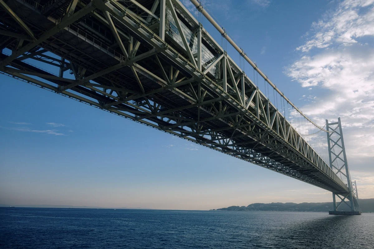
Akashi Kaikyō Bridge — engineering a 2 km span across the world's most hostile strait

Akashi Kaikyō Bridge — engineering a 2 km span across the world's most hostile strait

The Akashi Kaikyō Bridge (opened 1998) holds a 1,991-metre main span across the Akashi Strait — a crossing of 7-knot tidal currents, 110-metre depths, and an active fault. This case study traces every forced decision: why suspension beat cable-stayed at world-record scale, how 290 factory-wound PPWS strands replaced aerial spinning, how the world's largest wind-tunnel programme produced vertical stabilizer plates that hold the deck stable at 80 m/s, and how the January 17, 1995 Kobe earthquake shifted a tower foundation 1.3 metres mid-construction — extending the main span by 0.8 metres — while causing only one month of delay.
Engineering Marvel Teardown
2026. 5. 30. · 23:26
구독 4개 · 콘텐츠 14개
On the night of May 11, 1955, the passenger ferry Shiun Maru capsized in a sudden storm in the Akashi Strait between Honshu and Awaji Island. One hundred and sixty-eight people drowned. It was the worst domestic maritime disaster in postwar Japan, and it was not the strait's first such accident — the six-kilometre crossing between Kobe and Awaji had claimed lives repeatedly through the ferry era. 1 Public outrage after the Shiun Maru sinking forced a political reckoning: the strait needed a fixed crossing, not a ferry service.
The engineering consequences of that political decision took four decades to materialize. The structure that opened on April 5, 1998 — the Akashi Kaikyō Bridge, known in English as the Pearl Bridge — carries a main span of 1,991 metres, the longest of any suspension bridge for 24 years. 1 It crosses a strait where tidal currents exceed 7 knots, water depth reaches 110 metres, and the seafloor sits atop an active fault that ruptured in a magnitude-6.9 earthquake while the bridge was under construction. That earthquake moved the foundations. The engineers recalculated, adjusted two deck panels by 0.4 metres each, and opened the bridge on its original schedule. 2
The Akashi Kaikyō Bridge is not a record-holder that happened to survive hard conditions. Every design decision — the structural type, the deck geometry, the cable-spinning method, the caisson dimensions, the seismic tolerances — was forced by a site that the Japan Society of Civil Engineers described in 1967 as posing "extreme design and construction conditions unprecedented among the world's long-span bridges." 2

The Honshu–Shikoku project and the case for the east route

The Akashi Kaikyō Bridge is one piece of a larger political and infrastructure enterprise: the Honshu–Shikoku Bridge Project, three parallel road corridors linking Japan's main island to the island of Shikoku across the Seto Inland Sea. The three routes — east (Kobe–Naruto), central (Kojima–Sakaide), and west (Onomichi–Imabari) — together required 17 bridges and three decades of construction. 3
The east route, anchored by the Akashi Kaikyō Bridge, carried the longest single span. A bridge across the Akashi Strait had first been surveyed by the Kobe city government in 1957, incorporated into the national comprehensive development plan in 1969, and formally approved in 1973 at a main span of 1,780 metres. 1 That earlier design assumed a combined road-rail deck — a structural decision with major implications for load, truss depth, and cost. The 1973 project was shelved as Japan's post-oil-shock economy contracted.
When the project restarted in 1988, the rail deck was dropped. A pure highway design reduced the dead load on the deck, which in turn allowed a slimmer truss girder profile for the same span — a meaningful weight saving at a main span approaching 2 kilometres. The revised design accepted a main span of 1,990 metres (later modified to 1,991 m by the earthquake). Six lanes of expressway, 35.5 metres wide, with a navigation clearance of 65 metres above mean sea level. 2
The total project — all three routes combined — was designed to stimulate regional commerce and industrial development on Shikoku, which had no fixed link to the Japanese mainland until the central route's Seto Ohashi opened in 1988. Construction of the Akashi Kaikyō site began formally in May 1988, employing more than 100 contractors over a 10-year programme. 3

Suspension versus cable-stayed: where structural logic forced the choice

In 1988 the world's longest completed suspension bridge was the Humber Bridge in the United Kingdom, with a 1,410-metre main span. The Akashi design required 40% more. That scale difference is not just quantitative — it changes which structural form is physically viable.
Cable-stayed bridges work efficiently up to approximately 1,000–1,100 metres because their stay cables, anchored at tower heads, exert axial compression into the deck throughout their length. That self-anchoring efficiency is the cable-stayed bridge's strength, but it also defines its ceiling: as the main span grows, the horizontal component of cable force in the outermost stays creates extreme compressive forces in the deck, demanding heavier deck sections, which in turn requires even more cable force. The system spirals against itself beyond about 1,100 m. 2
The suspension bridge side-steps this problem. Main cables run over towers and anchor into massive concrete anchorages at each end; vertical suspenders hang the deck. The deck carries bending from traffic loads but is not subjected to the large horizontal compression of a cable-stayed system. The catenary geometry of the main cable means that as span increases, the required cable sag increases roughly in proportion — so the structural efficiency of the form does not collapse at record spans the way cable-stayed systems do.
At 1,991 metres, suspension was not a preference — it was the only form that could work.
The deck form required an equally decisive trade-off. A closed steel box girder of the type used on the Severn Bridge (1966) and Humber Bridge (1981) is aerodynamically efficient — its smooth soffit slips through wind without creating separated flow. But at 1,991 m, the box girder's stiffness against twisting (torsional rigidity) falls below the threshold needed to prevent flutter at the design wind speeds required for the Akashi Strait. The Tacoma Narrows collapse of 1940 had already demonstrated that long, shallow plate girders flutter catastrophically; the Severn-type box was an aerodynamic improvement over the plate girder but was designed for shorter spans in less exposed locations.
The Akashi design chose an open stiffened-truss girder instead: a 14-metre-deep, 35.5-metre-wide triangulated truss running the full length of the bridge. An open truss does not generate the same smooth aerodynamic envelope as a box girder, but its lattice structure allows wind to pass through rather than act on the full projected area of the deck. This significantly raises the flutter threshold. 2 The truss also provides the deck with the torsional stiffness the box girder could not reliably deliver at this span. The trade-off was increased wind drag overall, managed through the additional aerodynamic devices described below.

Aerodynamic engineering: designing for 80 m/s

The Akashi Strait sits in the path of Pacific typhoons, and the bridge's design wind speed is 80 m/s (288 km/h). That figure is not a worst-case estimate — it is the design envelope within which the structure must perform without failure or unacceptable oscillation. 4
To validate the aerodynamic design, the Honshu-Shikoku Bridge Authority commissioned the Public Works Research Institute to build what was, at the time, the world's largest wind tunnel facility. Engineers tested full-section models under both laminar and turbulent flow conditions, calibrating their predictions of flutter onset, vortex shedding response, and buffeting loads. The wind tunnel work took more than a decade to complete. 2
The single most important innovation from that testing programme was the addition of vertical stabilizer plates along the centre line of the deck's undersurface. As James D. Cooper (then chief of bridge technology at the U.S. Federal Highway Administration) described after inspecting the completed bridge: these plates were installed specifically to raise the critical flutter speed — the wind velocity at which the deck begins to exhibit diverging oscillations. 2 Without them, the open-truss deck at 1,991 m span would flutter at a wind speed within the design envelope, rather than above it.
Each of the two towers carries 20 tuned mass dampers (TMDs), installed in phases as the tower construction advanced through its 30-segment stacking sequence. A TMD is a pendulum or sliding mass tuned to the tower's natural sway frequency; when wind excites the tower at that frequency, the TMD mass moves in opposition, dissipating energy and limiting amplitude. At Akashi Kaikyō the TMDs were required not just for the completed structure but during construction itself — a partially built tower has lower mass and higher natural frequency than the finished one, making it more susceptible to resonant wind excitation. 2
One operational consequence of the aerodynamic sizing is thermal. The deck spans 1,991 metres of open water under large diurnal temperature swings; on a full summer day, the bridge's total length changes by up to 2 metres due to thermal expansion and contraction. Expansion joints and the suspension system's natural flexibility accommodate this without constraint force buildup. 1
A 2026 academic paper by H. Yamada, T. Miyata, N. N. Minh, and H. Katsuchi — all of whom have published on Akashi's wind engineering since the 1990s — developed a direct complex-eigenvalue analysis method integrating a three-dimensional FEM of the bridge with aeroelastic force matrices, to predict coupled gust response across all vibration modes simultaneously. 5 The method refines the aerodynamic model established during the design phase and illustrates that Akashi Kaikyō continues to serve as the principal benchmark for long-span suspension bridge wind engineering nearly three decades after opening.

Tower and foundation engineering: caissons in raging tides

The Akashi Strait's tidal conditions set the physical boundary conditions for everything beneath the waterline. Peak tidal currents in the strait exceed 7 knots (approximately 3.6 m/s); water depth at the tower locations varies between 36 and 50 metres below sea level, with rock at up to 60 metres depth. No previous suspension bridge had placed open-water caisson foundations in conditions approaching this combination of depth, current speed, and seismic exposure. 2
The foundation system used a purpose-developed technique: the laying-down caisson method. A hollow steel caisson — 80 metres in diameter and 70 metres tall — was fabricated onshore, towed horizontally to the construction site by tugboat (lying on its side in shallow water), then upended and sunk onto a pre-dredged seafloor. Once positioned and levelled, the caisson was filled with concrete to form the permanent tower base. The 80-metre diameter was required to distribute the 181,400-tonne vertical load from each tower across the seabed without exceeding the bearing capacity of the stratified alluvial and sedimentary geology below. 2 1
  • 2P tower (Kobe side): seafloor at 40–50 m depth; caisson base at 60 m; local geology — alluvial and diluvial layers over the competent Akashi formation
  • 3P tower (Awaji side): seafloor at 36–39 m depth; caisson base at 57 m; similar stratigraphy
Anti-scour protection around each caisson consists of a 2-metre-thick granular filter layer extending 10 metres from the caisson face, topped by an 8-metre riprap layer — necessary because the 7-knot currents that prevent ferry navigation are fully capable of eroding the seafloor around an unprotected foundation over decades.
The anchorages posed a different set of problems. Each anchorage block is 63 metres × 84 metres in plan and contains roughly 350,000 tonnes of concrete. 1 On the Kobe side, granite bedrock outcrops near the surface, allowing relatively conventional excavation and a circular slurry-wall retaining structure 85 metres in diameter and 2.2 metres thick, excavated to 61 metres below mean sea level in open air before being filled with compacted concrete. 2 The Awaji anchorage encountered softer, more complex soils and required temporary support through steel pipe piles and ground anchors before the structural concrete could be cast.
Each tower rises in 30 prefabricated steel segments, each approximately 10 metres tall, stacked and welded in sequence. Laser survey control was used throughout — at 282.8 metres above sea level, a cumulative verticality error of even a few centimetres at each of 30 joints would produce unacceptable geometric deviation at the saddle that carries the main cable. 2

PPWS cable spinning: why the old method could not scale

The main cables of the Akashi Kaikyō Bridge are 1.12 metres in diameter. Each cable contains 36,830 individual wires, each wire 5.23 mm in diameter, individually galvanized against corrosion. Laid end to end, the total wire length across both cables is approximately 300,000 km — 7.5 circumnavigations of the Earth. 1
Spinning those cables required a method that could not have been imported directly from earlier suspension bridge practice. The traditional aerial spinning (AS) method — developed by John Roebling for the Brooklyn Bridge and used on all major suspension bridges through the late 20th century — involves running individual wires back and forth across the span using a revolving spinning wheel on a working cable, accumulating wires in-place into bundles. The method works at spans up to roughly 1,500 metres, but at 1,991 metres, the sheer volume of individual wire-handling operations at height, over open water, in Akashi Strait currents, would have made construction both dangerous and logistically unworkable. 2
The method chosen instead was PPWS — Prefabricated Parallel Wire Strand. Rather than spinning individual wires in the field, factory workers assembled complete wire bundles (strands) onshore. Each strand contained 127 wires, was wound to a continuous length of 4,085 metres (exactly the distance from anchorage to anchorage over the two tower saddles), and was coiled onto a spool for transport. 2
The construction sequence:
  1. A helicopter flew the initial guide wire over the strait, draping it between tower tops.
  2. Suspended catwalks — the working platforms for cable installation — were rigged on the guide wire.
  3. Each factory strand was pulled from one anchorage, over both tower saddles, to the opposite anchorage, where it was fixed to the steel anchor frame.
  4. This was repeated 290 times to form each cable's full cross-section of 290 strands × 127 wires.
  5. A hydraulic cable-compaction machine then squeezed the 290 strands into a circular 1.12-metre section, and clamps locked the geometry.
The steel itself was non-standard. The wires at Akashi Kaikyō have a tensile strength of 180 kg/mm² — significantly above the 160 kg/mm² typical of contemporaneous suspension bridge cable wire. 2 That 12.5% strength premium directly reduced the total number of wires required for the same cable force, cutting material volume and installation time. It also allowed the suspension system to be designed with two hangers per deck panel rather than the four hangers typical on older suspension bridges — halving the number of individual high-altitude connections that had to be made in the cable-spinning and deck-erection phases.
Cooper's assessment for the FHWA was direct: the PPWS method "eliminates field wire spinning operations, thereby reducing the probability of accidents." 2 In the event, the entire 10-year construction programme produced six injuries and zero fatalities — a safety record that Cooper called "world class." 2
Akashi Kaikyō Bridge from the water — towers and cables visible in calm conditions
The two main cables run 3,910 m from anchorage to anchorage, each carrying 290 factory-wound strands of 127 wires. The 1.12 m cable diameter reflects the highest-strength bridge wire available at the time of construction. 1

The 1995 Kobe earthquake — when the earth reset the span

At 5:46 a.m. on January 17, 1995, an Mw 6.9 earthquake struck the region directly beneath the Akashi Kaikyō construction site. The epicentre of the Great Hanshin–Awaji earthquake (also called the Hyogo-ken Nanbu earthquake) was located approximately 20 kilometres west of Kobe — between the two bridge towers. 2
The construction state at the time of the earthquake was, from an engineering documentation perspective, an unusual one: only the two towers and the four anchorages were complete. The stiffened-truss deck panels had not yet been installed. This meant that the earthquake acted on pure structural elements — caissons, anchorage blocks, and tower shafts — without the complicating presence of a deck, and engineers could later reconstruct exactly what the seabed movements had been.
The Nojima Fault ruptures across Awaji Island's northern tip. Its surface expression — a visible ground crack — emerged approximately 2 kilometres from the Awaji-side anchorage. The fault passed between the two tower foundations. In the motion, the Awaji-side tower (3P) displaced 1.3 metres to the west relative to the Kobe-side tower; the Awaji anchorage moved 1.4 metres west. The 3P tower settled 0.2 metres vertically; the Awaji anchorage rose 0.2 metres. 2
The net effect on the bridge geometry: the centre-to-centre distance between tower foundations increased by 0.8 metres — from the design value of 1,990 m to approximately 1,990.8 m. The south side span increased by 0.3 metres. Main cable sag, had the cables been installed, would have decreased by 1.3 metres given the increased horizontal span. 2
Critically, the towers and anchorages sustained no structural damage. Cooper's 1998 assessment characterized the event as providing "a full-scale test of the tower foundation response" — and the design passed. 2 The caissons had been designed to withstand an Mw 8.5 earthquake at a 150-kilometre epicentre distance; they experienced an Mw 6.9 event centred directly between them and performed as designed. A cable-compaction machine on the catwalks was lightly damaged and quickly repaired.
The design revision was geometrically simple but structurally careful: two of the stiffened-truss deck panels at mid-span were each lengthened by 0.4 metres, absorbing the 0.8-metre span increase. The revised total main span became 1,991 metres — the figure on every specification sheet since. Total construction delay from the earthquake: approximately one month. 1
The earthquake also validated something the designers could not have predicted they would need: the two-hinge stiffened-truss deck system. A two-hinge system allows the structure to pivot at the tower top connections under differential support displacement, rather than developing large bending moments at those connections. Had the deck been installed before January 17, 1995, the differential settlement of 0.2 metres at each tower base would have induced bending demands in any deck with fixed end conditions. The two-hinge design absorbed the movement without stress consequences.
In 2025, two papers presented at the 12th World Conference of Earthquake Engineering (12WCEE) revisited the Akashi Kaikyō seismic record: one re-examined the seismic design methods and their measured performance during the Great Hanshin earthquake; the other analysed long-period ground motions recorded at the construction site. 6 These papers confirm that the bridge's construction-phase earthquake exposure remains an active area of geotechnical and structural research three decades later.

Construction in extremis

The ground-breaking ceremony took place on April 26, 1986; formal site construction began May 1, 1988. The project employed more than 100 contractor organizations in a programme that ran 10 years. 3
Marine logistics presented a persistent challenge. Akashi Strait is an active commercial shipping lane — second only to the Strait of Dover in traffic density for its width. Every barge, crane vessel, and material delivery had to be timed around the tidal cycle to avoid the worst of the 7-knot current pulses. Construction diving operations in the strait required careful tidal scheduling; even brief current speed reductions during slack tide were narrow windows. The working catwalk — the suspended platform on which cable workers operated during PPWS installation — was exposed to full strait weather including typhoon-force winds, and work had to be suspended whenever surface wind speeds exceeded operational safety thresholds.
The bridge's illumination system reflects a commitment to long-term civic function: 1,737 lights (1,084 on the main cables, 116 on each tower, 405 on the deck soffit, 132 at the anchorages) driven by RGB colour-control electronics producing 28 programmable patterns for national holidays, memorial days, and regional events. 1 The lighting was designed as a permanent navigation landmark for the strait's shipping, not only as aesthetic spectacle.
Total construction cost was approximately ¥500 billion (approximately US$3.6 billion at 1998 exchange rates). 1 The bridge opened on April 5, 1998, presided over by then Crown Prince Naruhito and Crown Princess Masako. Since opening, the bridge has operated a ¥2,300 toll per crossing and handles approximately 23,000 vehicles per day. 1

Specifications

ParameterValue
Main span1,991 m
Total bridge length3,911 m
Side spans960 m each
Tower height above sea level282.8 m (297.3 m including saddle)
Tower construction30 prefabricated steel segments, laser-levelled
Main cable diameter1.12 m
Wires per cable36,830 (290 strands × 127 wires)
Wire tensile strength180 kg/mm²
Wire diameter5.23 mm
Total wire length~300,000 km
Cable-spinning methodPPWS (Prefabricated Parallel Wire Strand)
Deck typeOpen stiffened-truss girder, 14 m deep × 35.5 m wide
Design wind speed80 m/s (288 km/h)
Design seismic standardMw 8.5 at 150 km epicentre distance
TMDs per tower20
Navigation clearance65 m above mean sea level
Caisson diameter80 m
Caisson height70 m
Anchorage plan dimensions63 m × 84 m
Anchorage concrete volume~350,000 tonnes per anchorage
Construction periodMay 1988 – April 1998 (10 years)
Construction cost¥500 billion (~US$3.6 billion, 1998 rates)
Daily traffic~23,000 vehicles
Toll¥2,300 per crossing
Sources: 1 2 7
통계 카드를 불러오는 중…

Legacy and influence on subsequent bridge engineering

The Akashi Kaikyō Bridge did not just hold a record — it changed the toolkit available to the next generation of long-span bridge engineers in five concrete ways.
PPWS as the new standard for very long spans. The prefabricated parallel wire strand method has been adopted on every major suspension bridge built since Akashi. Its advantages — factory quality control over wire alignment, field assembly confined to strand pulling rather than individual wire spinning, elimination of the spinning-wheel rigging system at height — compound at spans above 1,500 metres where the AS method becomes logistically unsustainable. The 180 kg/mm² high-strength wire standard that Akashi's engineers specified has since become the industry baseline for long-span cable work. 2
Dry-air injection for cable corrosion management. Each of Akashi Kaikyō's main cables contains 36,830 galvanized wires in close contact. Moisture infiltration into the cable interior, impossible to prevent entirely with conventional wrap-and-paint systems over decades, triggers corrosion that is invisible until individual wires fracture. The operator, JB Honshi (Honshu-Shikoku Bridge Expressway Company), implemented a dehumidified air injection system that continuously circulates dry air through sealed cable sections, maintaining relative humidity below the threshold for electrochemical corrosion onset. A 2021 review in Applied Thermal Engineering (DOI: 10.1016/j.applthermaleng.2021.117549) describes dehumidification as a direct legacy of Akashi Kaikyō's maintenance programme; the technique has since been applied to other long-span suspension bridges worldwide as a viable alternative to full cable replacement. 8
Wind tunnel methodology and flutter prediction. The world-largest wind tunnel constructed for Akashi's design phase — and the research programme it enabled — produced new methods for predicting coupled flutter response in long-span suspension bridges under turbulent conditions. The 2026 paper by Yamada et al. directly extends this design-phase research into a general analytical framework for complex flutter-mode coupled gust response, using Akashi as the benchmark validation case. 5 The bridge remains the primary empirical reference for any researcher working on the aerodynamics of very long suspension spans.
Seismic isolation philosophy for open-water foundations. The earthquake test of January 1995, inadvertent though it was, confirmed that large-diameter open-water caissons designed to the Japanese seismic code can withstand direct fault rupture beneath the structure without collapse or fracture, provided the deck system can accommodate the resulting differential displacement. This finding — a real-world proof rather than a model prediction — has informed the seismic design of subsequent marine infrastructure in high-seismicity environments. The 12WCEE 2025 papers represent continued academic analysis of what the 1995 event reveals about long-period ground-motion characterisation at coastal sites. 6
The span record and its successor. The Akashi Kaikyō Bridge held the world record for the longest suspension bridge main span from April 1998 to March 18, 2022 — 24 years. The record was broken by Turkey's 1915 Çanakkale Bridge, which opened with a main span of 2,023 metres, surpassing Akashi by exactly 32 metres. 9 The Çanakkale Bridge's span of 2,023 m references the centennial year of the Turkish Republic. Its design — by COWI and PEC, built by a consortium including South Korean and Turkish contractors — drew directly on PPWS cable technology and the aerodynamic knowledge codified at Akashi. The lineage from Akashi to Çanakkale is not metaphorical: the same cable-spinning system and the same computational approach to deck flutter prediction appear in both structures, scaled to a span 32 metres longer. Cooper had noted in 1998 that Japanese engineers were already studying the feasibility of a 2,400-metre main span — an engineering boundary that remains unbuilt but no longer theoretical. 2
링크 미리보기를 불러오는 중…
콘텐츠 카드를 불러오는 중…
The Akashi Kaikyō Bridge's 30th anniversary falls on April 5, 2028. No major commemorative projects or advance coverage had emerged as of May 2026. What has accumulated instead is a growing body of academic work — the Yamada flutter paper, the two 12WCEE seismic papers, the cable corrosion maintenance literature — that treats the bridge not as a historical artefact but as an ongoing experimental platform for the field's most demanding unsolved problems in wind and earthquake engineering. The bridge is currently the second-longest suspension span in the world. Its status as the most thoroughly instrumented and studied long-span bridge in history is not something the 1915 Çanakkale Bridge has displaced.
Cover image: Akashi Kaikyō Bridge, Pexels royalty-free stock photo

이 콘텐츠를 둘러싼 관점이나 맥락을 계속 보강해 보세요.

  • 로그인하면 댓글을 작성할 수 있습니다.