Channel Tunnel — engineering the 38 km hole under the English Channel

Channel Tunnel — engineering the 38 km hole under the English Channel

A 5,500-word engineering case study tracing the Channel Tunnel from the 1882 first attempt through the 1994 opening to 2026 operations. The article follows the chain of forced decisions: chalk marl geology selection (28-year site investigation, 166 marine boreholes) drove the asymmetric TBM fleet (6 UK open-face vs. 5 French EPB machines that ran closed mode for the first 5 km); the three-bore configuration with a positive-pressure service tunnel bored 1 km ahead as a geological pilot is shown as a dual-purpose safety and surveying solution; the 50°C cooling problem required Europe's largest chilling system (480 km of pipes, now upgraded to Trane CenTraVac units saving 33% energy); and the 1996/2008 fires validated the cross-passage evacuation philosophy while driving the SAFE station fibre-optic detection programme and the current Siemens replacement (≈£90M). Legacy section covers EPB general-purpose validation, Crossrail service gallery inheritance, ElecLink 1 GW interconnector, Getlink's record €859M 2025 EBITDA, and the March 2025 St Pancras Highspeed MoU targeting Cologne/Frankfurt/Geneva routes.
Engineering Marvel Teardown
2026/5/31 · 23:31
購読 4 件 · コンテンツ 14 件
On the morning of December 1, 1990, a British worker named Graham Fagg swung a pickaxe through the remaining chalk at the face of the service tunnel and shook hands with Philippe Cozette, his French counterpart coming from the other direction. A BBC commentator described Fagg as "the first man to cross the Channel by land for 8,000 years." 1 The precision of that handshake is, in some ways, the whole story: after boring from opposite shores toward a target they could not see, two TBM crews met with a horizontal misalignment of 30 cm and a vertical error of 8 cm — and the tunnel came out 2 cm shorter than estimated. 1 For a 50 km undersea bore in the mid-20th century, that is an extraordinary result.
The Channel Tunnel — formally the Channel Tunnel (physical infrastructure), operated by Getlink through its Eurotunnel division — is a 50.46 km (31.35 mi) railway tunnel connecting Folkestone in Kent, England to Coquelles near Calais in northern France. 2 Its 38 km undersea section is the longest of any rail tunnel running beneath the sea — a record it still holds. 1 The tunnel was officially opened on May 6, 1994, by Queen Elizabeth II and French President François Mitterrand, with commercial services beginning in phases through the end of that year. By the time Getlink released its Q1 2026 results, the tunnel had carried 537 million passengers and over 109 million vehicles since opening. 2
What makes the Channel Tunnel a lasting engineering case study is not the record figures — it is the chain of design decisions that forced each other. The choice of chalk marl as the boring stratum determined the TBM specifications. The TBM specifications determined why the two national teams used fundamentally different machines. The three-bore configuration was not an architectural preference; it was the structural solution to a fire safety problem that a road tunnel could not solve. Understanding the tunnel means following those decisions in order.

Profile, prehistory, and the financing gamble

The impulse to connect Britain and France beneath the Channel is not modern. In 1802, French engineer Albert Mathieu-Favier proposed a horse-drawn carriage tunnel lit by oil lamps, with a mid-Channel artificial island for ventilation and rest. The first serious attempt came in 1882–1883: a British TBM (tunnel boring machine) bored 1,840 m from Shakespeare Cliff while a French machine reached 1,669 m from Sangatte before the British military successfully lobbied to halt the project on grounds of invasion risk. 1 A second government-backed attempt began in 1974 and was cancelled on January 20, 1975 by the incoming UK Labour government — citing economic crisis and doubled cost estimates — at a cost of £17 million. One legacy survived: a 300 m experimental adit (Adit A1) bored from Shakespeare Cliff was preserved and later reused as the main construction access point for the 1988 project. 1
The third attempt acquired a different political character entirely. Margaret Thatcher's government insisted on no public money. The Treaty of Canterbury, signed February 12, 1986, established a privately-funded framework and created the Intergovernmental Commission (IGC) to oversee the project. 1 Four proposals were formally considered before the winning design was selected in April 1985: (1) the rail tunnel scheme by CTG/F-M (a consortium of five French and five British construction companies plus six banks); (2) Eurobridge, a 35 km suspension bridge with 5 km spans and an enclosed roadway tube suspended 70 metres above the sea using Parafil aramid fibre rope; (3) Euroroute, a combination of bridge approaches and a submerged tube between artificial islands; and (4) Channel Expressway, a pair of large-diameter road tunnels with mid-Channel ventilation towers. 1
The rail proposal won on four grounds stated in the government's assessment: least disruption to shipping, least environmental disruption, best protection against terrorism, and most likely to attract sufficient private finance. The road tunnel alternatives were ruled out specifically on ventilation — the engineering and safety difficulty of managing vehicle exhaust over a crossing that takes 35 minutes and cannot allow passenger windows to open was judged unacceptable. Driver mesmerisation (highway hypnosis on a monotonous undersea road) was also cited as a safety hazard that could not be designed away. 1
Financing was a Build-Own-Operate-Transfer (BOOT) concession: TransManche Link (TML), the bi-national joint venture of ten construction companies, designed and built the tunnel. Eurotunnel (now Getlink) was the separate legal entity that raised the money and would operate the tunnel. The initial cost estimate in 1985 prices was £2.6 billion; the final cost at completion was £4.65 billion in 1985 terms — an 80% overrun — equivalent to approximately £9.8 billion in 2025 pounds. Financing costs alone ran 140% above forecast. 1 The concession originally ran 55 years from 1987; in 1993 it was extended by 10 years to 65 years, expiring in 2052. British Rail and SNCF committed by Railway Usage Agreement to use half the tunnel's capacity, providing the revenue floor that made bank lending possible. 1
Work officially began December 1, 1987, and the Channel Tunnel Act received Royal Assent in July 1987.

The geology decision — finding the right stratum
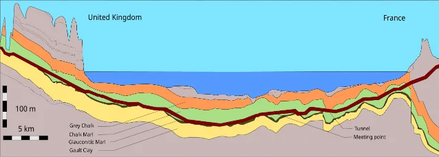
If one decision explains the Channel Tunnel more than any other, it is the choice to bore through a specific stratum of chalk marl that runs beneath the Channel floor at depths between 45 and 75 metres below sea level.
The English Channel's subsurface is a layered sequence of Cretaceous sedimentary formations, none of which would be obvious to a non-specialist as a candidate for tunnelling. The chalk marl (called craie bleue on the French side) is a 25–30 m thick band in the lower third of the Lower Chalk formation. It contains 30–40% clay content, making it effectively impermeable to groundwater while remaining soft enough to excavate efficiently with a rotating cutter head. It is strong enough to require minimal immediate support after cutting — unlike unstable clays — but yields readily to a TBM without the shattering that harder rock causes. 1 85% of the total tunnel length passes through chalk marl. 1
The optimal boring zone was the bottom 15 m of the chalk marl layer — a narrow band bounded by constraints above and below. Below it lies the Gault Clay, an older formation that swells and softens when it contacts water; boring into Gault Clay would increase stress on the tunnel lining over time and create ongoing structural maintenance problems. Above the chalk marl, the Upper and Middle Chalk are pervious, meaning groundwater from the seabed above would infiltrate the tunnel face. The chalk marl's clay content makes it the natural boundary between the drained upper chalk and the waterlogged strata below. 1
The route also had to avoid the Fosse Dangeard — an infilled Quaternary valley system extending 80 m below the present seabed, carved when sea levels were lower. The geological surveys identified its position, and the tunnel alignment was shifted as far north and as deep as possible to skirt it entirely. 1
Finding this stratum and characterising it along the full 50 km route required a site investigation programme that ran, in various phases, across 28 years (1958–59, 1964–65, 1972–74, and the definitive 1986–88 campaign). The final campaign included 166 marine boreholes, 70 land boreholes, and over 4,000 line-kilometres of marine geophysical survey. 1
Geological profile along the Channel Tunnel route showing chalk marl stratum, Gault Clay, and the Fosse Dangeard valley
Longitudinal geological cross-section through the chalk marl boring zone. The tunnel follows the bottom 15 m of the chalk marl band — above the waterlogged Gault Clay and below the pervious Upper Chalk. 1
The survey confirmed one critical asymmetry that shaped everything downstream. On the English side, the chalk marl dips at less than 5° with minor faults under 2 m displacement — geologically quiet and predictable. On the French side, the dip increases to 20°, the chalk is harder, more brittle, and more heavily jointed, and faults can displace strata by up to 15 m due to the Quenocs anticlinal fold. The first 5 km of the French bore fell outside the clean chalk marl entirely, through fractured and variable rock under high water pressure. 1 That asymmetry meant the two national teams could not use the same tunnelling machinery.
A 2025 paper in Rock Mechanics and Rock Engineering noted that even with this investigation, chalk behaviour in the NATM sections was underestimated: chalk marl stand-up times calculated using the modified RMR (Rock Mass Rating) method were found to have been overstated by 40–60% in the most jointed zones. 3 The tunnelling industry has since recalibrated chalk classification standards, in part using Channel Tunnel experience as the primary empirical dataset.

Three-bore architecture — the service tunnel as an engineering keystone
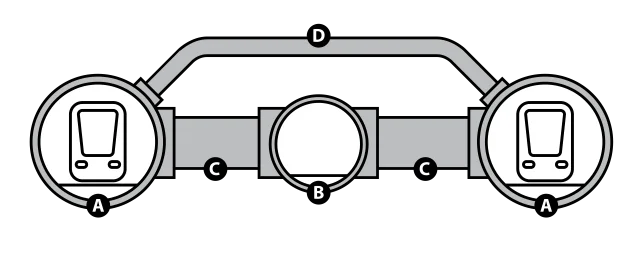
The Channel Tunnel is three tunnels, not one. The two running tunnels for rail traffic are each 7.6 m (25 ft) in internal diameter, bored 30 m (98 ft) apart centre-to-centre. Between them runs a 4.8 m (16 ft) service tunnel, centred geometrically between the two main bores. 1
The service tunnel is connected to both running tunnels by 270 cross-passages of 3.3 m diameter, spaced at 375 m (1,230 ft) intervals. 1 These passages serve three functions: emergency evacuation from a running tunnel in the event of fire or accident, maintenance access to equipment rooms installed at regular intervals, and supply of fresh air that is drawn through the cross-passage openings by the piston effect of passing trains. The service tunnel itself is maintained at slightly higher air pressure than the running tunnels — meaning that in any fire scenario, smoke cannot migrate backward into the evacuation route. This positive-pressure principle is the single most important safety feature of the entire configuration. 2
The two running tunnels are also cross-connected by 194 piston relief ducts of 2 m diameter, at 250 m (820 ft) spacing. 1 A train entering a 7.6 m bore at 160 km/h behaves hydraulically like a piston — it drives a pressurised slug of air ahead of it and creates a partial vacuum behind. Without relief, this piston effect would increase aerodynamic drag significantly (requiring more traction power), create pressure fluctuations affecting passenger comfort, and complicate the ventilation system. The piston relief ducts allow air to bleed laterally between the two running tunnels, equalising pressure across the bore before it can build. During design, engineers investigated whether the long tube with regularly spaced openings would function acoustically like a giant flute; testing confirmed it does not produce problematic resonances at train operating speeds. 4
The two undersea crossover caverns — built at 8 km from Shakespeare Cliff and 12 km from Sangatte — allowed trains to cross between running tunnels and were, at the time of construction, the largest artificial undersea caverns ever built: each 150 m long, 10 m high, and 18 m wide. 1 They remain essential to maintenance scheduling, as they enable bidirectional operation within individual tunnel segments when one main bore needs to be taken out of service.
Schematic cross-section of the Channel Tunnel's three-bore configuration, with service tunnel centred between the running tunnels and piston relief ducts connecting the two main bores
Three-bore cross-section: the 4.8 m service tunnel (centre) is maintained at higher air pressure than the flanking 7.6 m running tunnels. Cross-passages at 375 m intervals provide evacuation routes; piston relief ducts at 250 m intervals equalise aerodynamic pressure between the two main bores. 1
The service tunnel's most underappreciated engineering role was geological: it bored at least 1 km ahead of either main tunnel, acting as a continuous site investigation probe. When the TBMs encountered unexpected fracture zones, flooded joints, or softened strata, the service tunnel had already characterised those conditions and adjusted the main tunnel geometry and lining specification before the larger cutters arrived. The service tunnel was not a support structure — it was a running experiment that the main tunnels could learn from in real time. 4
The Service Tunnel Transport System (STTS) — 24 rubber-tyred vehicles guided by a buried wire, capable of 80 km/h and carrying payloads of 2.5–5 tonnes — provides the permanent maintenance artery. It also carries the fire response vehicles: two STTS platforms with firefighting pods are on duty at all times, with a maximum response time of 10 minutes to reach any point in the running tunnels. 1

The TBM fleet — 11 machines, two different problems
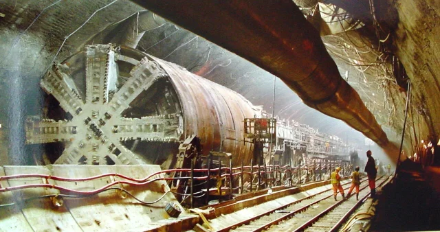
The practical consequence of the geological asymmetry between the English and French sides was that TML deployed two fundamentally different types of tunnel boring machine. In total, 11 TBMs were used: 6 from the UK (Shakespeare Cliff) and 5 from the French side (Sangatte). 1
The UK TBMs were open-faced machines. In open mode, the rotating cutter head excavates rock directly, the freshly cut face stands without support for long enough to install the precast concrete lining ring, and spoil is removed by a conveyor running behind the cutter head. Open-face machines are simpler, faster in stable ground, and generate less wear on mechanical seals. The consistent, predictable chalk marl of the English side — low dip angles, minimal fault displacement, low water inflow — made open-face boring the rational choice for all three UK drives. 1
The French TBMs were earth pressure balance (EPB) machines, capable of operating in both open and closed modes. In closed mode, the cutter head seals against the tunnel face and the excavated spoil fills a pressure chamber behind the cutters. A screw conveyor controls the rate at which spoil exits the chamber — by varying the screw's rotation speed, the operator adjusts how quickly material is removed, which in turn sets the back-pressure against the tunnel face. That back-pressure can be tuned to exactly match the hydrostatic pressure of groundwater at any given depth, preventing water inflow. 4 The French EPB machines ran in closed mode for the first 5 km through the fractured, high-pressure geology, then switched to open mode once they reached the predictable chalk marl. 1
The TBMs were manufactured by a joint venture of the Robbins Company (Kent, Washington, USA), Markham & Co. (Chesterfield, England), and Kawasaki Heavy Industries (Japan). The UK service tunnel and running tunnel TBMs were additionally designed by James Howden & Company Ltd (Scotland). Running tunnel TBMs bored to an 8.72 m outer diameter, leaving a 7.6 m internal diameter after the precast lining was installed; the service tunnel TBMs bored 5.76 m outer diameter for a 4.8 m internal bore. 1
The French TBMs were named after women: T1 Brigitte, T2 Europa, T3 Catherine, T4 Virginie, and T5 Pascaline (later renamed T6 Séverine for the final drive). 1 The UK machines used technical designations.
One of the TBMs underground during construction — the open shield design is visible in this view of the crossover chamber assembly area
A TBM shield in the crossover chamber area during construction. The Channel Tunnel's six UK-side machines were open-faced; France's five used earth pressure balance technology for the geologically complex first 5 km. 1
Segmental lining also diverged by nationality. The French side used 5 segments plus a key segment per ring, sealed with neoprene gaskets and grout-injected bolts. The UK side used 8 segments plus a key segment per ring for the main tunnels, with cast-iron linings deployed only in problem ground. 1 The precast concrete segments were manufactured at a dedicated factory on the Isle of Grain in the Thames estuary, using Scottish granite aggregate transported by ship from the Foster Yeoman Glensanda coastal super quarry in Loch Linnhe — the space constraints at Shakespeare Cliff made it impossible to operate a casting facility at the portal site. 1
The breakthrough happened in stages. On October 30, 1990, a 50 mm pilot hole connected the service tunnels — confirming alignment. The official handshake breakthrough followed on December 1, 1990: 30 cm horizontal, 8 cm vertical misalignment, tunnel 2 cm shorter than estimated. 1 The running tunnels connected in May–June 1991. The first full test run through the entire system took place on December 10, 1993. 1
What happened to the machines at the end differs as sharply as the machines themselves. The UK TBMs were driven steeply downward into the chalk at the end of their drives and buried in place — where they serve today as earthing electrodes for the tunnel's electrical system. One UK TBM was briefly displayed beside the M20 motorway in Folkestone before being sold for scrap. The French EPB machines were dismantled and components recovered; T4 Virginie survives as a monument at junction 41 of the A16 autoroute near Coquelles, with the inscription "hommage aux bâtisseurs du tunnel" (tribute to the builders of the tunnel). 1

Construction logistics — moving a mountain under the sea

At peak construction, the Channel Tunnel employed 15,000 workers and spent over £3 million per day. 1 The logistics of supplying a 50 km sub-sea bore from two shore portals — feeding lining segments, grout, plant, and people forward while continuously removing spoil — required independent temporary infrastructure on both sides.
On the UK side, a 900 mm narrow-gauge temporary railway served as the primary artery: workers, precast lining segments, cement, and equipment moved inward on the track; spoil returned outward on parallel conveyor belts. The access point was a 140 m marshalling area below Shakespeare Cliff, excavated using the New Austrian Tunnelling Method (NATM) — its first application in chalk marl. 1 The 300 m Adit A1 from the 1974 project was reused as the initial entry point and remains an access point to the service tunnel today. 1
On the French side, access came through a 55 m diameter, 75 m deep shaft at Sangatte, sunk with a grout-curtained perimeter to prevent water inflow through the variable near-surface geology. French spoil was pumped as a wet slurry to Fond Pignon, a disposal lagoon adjacent to the shaft. 1
The UK spoil disposal decision required more creativity. Approximately 5 million cubic metres of chalk emerged from the British drives. About 1 million m³ was used as fill for the terminal site; the remainder was deposited at Lower Shakespeare Cliff behind a reinforced concrete seawall, reclaiming 74 acres (30 hectares) of the foreshore from the sea. 1 Environmental approval required the spoil be contained in an enclosed lagoon to prevent dispersal of chalk fines into the marine environment. The resulting parcel of land was later developed into Samphire Hoe, a country park and nature reserve that also hosts the UK-side cooling plant. (Note: Practical Engineering cites the reclamation at 111 acres; Wikipedia and the official Samphire Hoe documentation cite 74 acres / 30 hectares. This article uses the documented 74-acre figure.) 1
Ten workers were killed during the construction of the Channel Tunnel between 1987 and 1993, eight of them British. The majority of fatalities occurred during the early months of boring, before the project had fully implemented safety protocols for undersea compressed-air operations and heavy segment handling in confined spaces. After multiple lawsuits and investigations, safety practices improved substantially and the latter phase of the project had a much lower incident rate. 1

Technical specifications — railway systems and the 50°C cooling problem

Operating a railway in an enclosed 50 km tube under the sea creates thermal and mechanical conditions that surface railways never face. The Channel Tunnel's engineering solution to those conditions is worth understanding in detail.

Electrification and signalling

The tunnel runs on 25 kV 50 Hz AC overhead contact wire, with the nominal contact wire height at 6.03 m above rail. 1 Power is fed equally from the English and French national grids via substations at both terminals; in an emergency, the tunnel's 20,000 light fittings and plant equipment can be powered entirely from one side. 1
The signalling system is TVM-430 (Transmission Voie-Machine, generation 4.30) — cab signalling that feeds speed targets and authority limits directly to a driver's in-cab display, with automatic train protection that intervenes if the train exceeds the indicated speed. TVM-430 is the same system used on LGV Nord (Paris–Lille high-speed line) and High Speed 1, allowing trains to enter and exit the tunnel without stopping for signal checks. 1
Maximum operating speed is 160 km/h (99 mph); the track geometry allows 200 km/h (120 mph). The discrepancy exists because testing revealed that the piston relief duct design, as originally sized, produced extreme lateral forces on trains at 200 km/h. 1 Restrictors were installed in the ducts to damp the effect, but operating speed was also conservatively capped. The loading gauge height is 5.75 m (18 ft 10 in) — generous enough to accept the Eurotunnel Shuttle wagons, the largest railway wagons in the world, which carry loaded heavy goods vehicles on their decks. 1

Track system

Ballasted track was rejected outright for the tunnel interior. The stability problems of ballast under confined high-speed conditions — the risk of ballast projection from high-speed trains, drainage complexity, and the difficulty of maintaining precise geometry in an environment where resurfacing requires full tunnel possession — made it unsuitable. 1
The tunnel uses the Sonneville Low Vibration Track (LVT) system, designed by Roger Sonneville. 100 kg pre-cast concrete blocks support UIC60 (60 kg/m) rails of 900A grade at 60 cm centres. Each block sits on a 12 mm closed-cell polymer foam pad inside a rubber boot, which isolates block movements from the concrete invert and absorbs the vibration that would otherwise propagate into the tunnel structure. Approximately 334,000 Sonneville blocks were manufactured at an automated factory on the Sangatte site; rails, blocks, boots, and pads were assembled outside the tunnel and lowered in as completed track sections. 1

Cooling

Engineers calculated during design that heat from traction equipment and aerodynamic drag would raise tunnel temperature to 50°C (122°F) without active cooling — high enough to damage equipment and cause passenger distress. 4 The design target was 30°C (86°F).
The original cooling system was, at the time of installation, Europe's largest: 480 km (300 mi) of 61 cm (24 in) diameter pipes circulating 84 million litres (18 million imperial gallons) of chilled water, fed by eight York Titan chillers running on R22 HCFC refrigerant at the two portal buildings. 1
In 2016, the Montreal Protocol's global phase-out of R22 triggered a full replacement. The original chillers were decommissioned and replaced with four Trane Series E CenTraVac large-capacity chillers — two at each portal — using Honeywell R1233zd(E), a refrigerant with near-zero global warming potential. The new units are rated at 2,600 kW to 14,000 kW each, maintain the tunnel at 25°C (77°F) rather than 30°C, and in their first year of operation consumed 4.8 GWh less electricity than the old chillers — a 33% energy reduction worth approximately €500,000 annually for Getlink. 1

Specifications summary

ParameterValue
Total tunnel length50.46 km (31.35 mi)
Undersea section37.9 km (23.5 mi)
Running tunnel internal diameter7.6 m (25 ft)
Service tunnel internal diameter4.8 m (16 ft)
Running tunnel spacing (centres)30 m (98 ft)
Cross-passage diameter / spacing3.3 m / 375 m
Piston relief duct diameter / spacing2 m / 250 m
Crossover cavern dimensions150 m × 10 m × 18 m
TBM bore diameter (running)8.72 m outer
TBM bore diameter (service)5.76 m outer
Electrification25 kV 50 Hz AC overhead
SignallingTVM-430 cab signalling + ATP
Operating speed160 km/h
Design speed200 km/h
Track systemSonneville LVT, UIC60 rail, 60 cm spacing
Cooling pipe length480 km
Cooling pipe diameter61 cm
Cooling water volume84 million litres
Tunnel depth below sea level (max)75 m
Tunnel depth below seabed (average)45 m
Construction start1 December 1987
Opening (official)6 May 1994
Initial cost estimate (1985 prices)£2.6 billion
Final cost (1985 prices)£4.65 billion (80% overrun)
Concession expiry2052
Sources: 1 4

Fire safety — a philosophy tested by real fires

The Channel Tunnel's fire safety architecture rests on a single geometric principle: separation. In any fire, passengers in the burning running tunnel have a route to a place that fire cannot reach. That place is the service tunnel, sealed at positive pressure, connected via the closest cross-passage fire door, and served by its own ventilation system, communications network, and STTS vehicles.
The cross-passage fire doors are rated to withstand fire for at least 30 minutes — longer than the 27-minute transit time of a loaded shuttle. Each running tunnel has a 250 mm (10 in) water main running its full length, with hydrant points at 125 m (410 ft) intervals, fed from the service tunnel water supply. 1 Each shuttle wagon has its own fire detection system using ion, UV radiation, smoke, and gas sensors — capable of triggering onboard suppression. 1
The fire safety philosophy was tested, severely, on November 18, 1996: a fire broke out on a heavy goods vehicle aboard a southbound HGV shuttle. The fire reached 1,000°C (1,800°F) at its core and caused severe damage to 46 m of tunnel lining, with approximately 500 m affected to varying degrees. No one was killed. The exact cause was never definitively established; arson was suspected. Full tunnel operation was restored after six months of repair. 1
A second significant fire occurred on September 11, 2008, in a freight shuttle approximately 11 km from the French entrance. Again, no fatalities; the evacuation through the cross-passages into the service tunnel functioned as designed. Repair costs reached €60 million, and full service resumed on February 9, 2009 — approximately five months after the fire. 1 A smaller fire on January 17, 2015, evacuated 38 passengers and four Eurotunnel staff through cross-passage CP 4418, with STTS vehicles transporting them to France. 1
The 2008 fire prompted a more systematic post-incident response. Eurotunnel subsequently deployed four SAFE (Station d'Attaque du Feu) firefighting stations, each 900 m long, positioned strategically through the tunnel. Each SAFE station integrates AP Sensing linear heat detection — a distributed temperature sensing (DTS) fibre-optic system that can locate a heat source within the tunnel to a specific metre — with a Fogtec high-pressure water mist suppression system capable of targeted firefighting even in high-airflow conditions. 5 The system was validated in April 2010 in full-scale live fire tests in Spain using fires rated at 100–150 MW — roughly equivalent to 40 cars burning simultaneously. 5
In 2024, Getlink's Infrastructure Director Dan Hughes disclosed that the tunnel's fire detection system is undergoing complete replacement in a major digitalisation project with Siemens, at an investment of approximately £90 million. 6 Simultaneously, the Channel Tunnel Safety Authority (CTSA) 2026 work plan rated lithium-ion battery EV fire risk — from electric passenger cars loaded onto shuttle wagons, EV lorries, and electric bicycles — as the top-priority (A1) safety supervision item for the year. 7 The battery fire risk profile differs from the HGV fires in the 1996 and 2008 incidents: lithium battery fires are harder to extinguish with water, can re-ignite hours after apparent suppression, and involve different chemical suppression requirements. How an enclosed undersea tunnel manages this class of fire is the next design problem the SAFE station architecture will face.

Legacy and the tunnel's second act

The American Society of Civil Engineers named the Channel Tunnel one of the Seven Wonders of the Modern World in 1994 — alongside the CN Tower, Empire State Building, Golden Gate Bridge, Itaipu Dam, Panama Canal, and the Netherlands North Sea Protection Works. 1 That recognition reflects the engineering genuinely accumulated in the project, not just its scale.
The tunnel holds the world record for the longest undersea section of any tunnel at 37.9 km, a record that stands 30 years after opening. It is the third-longest railway tunnel overall, behind the Gotthard Base Tunnel (Switzerland, 2016) and Seikan Tunnel (Japan, 1988). 1 The breakthrough alignment precision — 30 cm horizontal, 8 cm vertical — became a surveying standard for the global TBM industry.
The Channel Tunnel's influence on subsequent TBM-based megaprojects runs through several specific channels. The EPB machine in variable geology — deployed on the French side's first 5 km — proved that a single machine could handle the full spectrum from fractured rock under high water pressure to clean chalk marl, simply by switching between operating modes. This validated EPB as a general-purpose platform for complex urban and sub-sea environments. The three-bore configuration with a central service tunnel as pilot and safety spine became the reference design for large undersea projects. Crossrail (now the Elizabeth line in London), which completed in 2022 with twin 6.2 m bores, used a service gallery philosophy directly inherited from Channel Tunnel experience. The spoil management approach — using excavated material for structured land reclamation rather than treating it as pure waste — was adopted at Crossrail (producing Wallasea Island nature reserve in Essex) and is now standard practice on major urban TBM projects.
In 2021, the ElecLink HVDC interconnector — 1,000 MW capacity, 320 kV DC, 51 km — was installed through the Channel Tunnel's service tunnel: a power cable connecting the British and French electricity grids that may not have been feasible without the tunnel infrastructure already in place. 1 The interconnector is capable of supplying approximately 1.6 million homes.
The commercial picture has stabilised, if not flourished. Getlink's 2025 full-year results reported consolidated EBITDA of €859 million — above guidance, and a record — with Eurotunnel segment EBITDA of €667 million, also a record. 8 Eurostar passenger numbers reached 11.81 million in 2025, also a record. 8 In March 2025, Getlink and London St. Pancras Highspeed signed a Memorandum of Understanding to develop new direct high-speed rail services from London to Cologne, Frankfurt, Geneva, and Basel — bringing the tunnel's expansion ambitions into measurable shape. 9 The European Commission's November 2025 plan to accelerate high-speed rail across Europe, targeting a functional network by 2040, names cross-Channel connectivity as a priority, with binding cross-border bottleneck timelines to be set by 2027. 10
The tunnel's engineers could not have known in 1986 that they were also building a route for a power interconnector, a template for urban TBM logistics, and an evolving fire safety laboratory. Fernando Torres at the Eastern Engineering Group put the operational durability plainly in 2026: "Infrastructure of this kind is never truly finished. It has to keep absorbing new regulatory, operational, and commercial realities without losing the reliability that made it valuable in the first place." 2 That observation applies precisely to the lithium battery challenge the CTSA is now managing, the Siemens fire detection replacement currently under way, and the high-speed rail expansion whose financial and political groundwork is still being laid.
The chalk marl stratum that made all of it possible was identified through 28 years of boreholes, seismic surveys, and geological cores. The tunnel that followed it is the longest undersea railway in the world, and it is 30 years into a concession that runs to 2052.
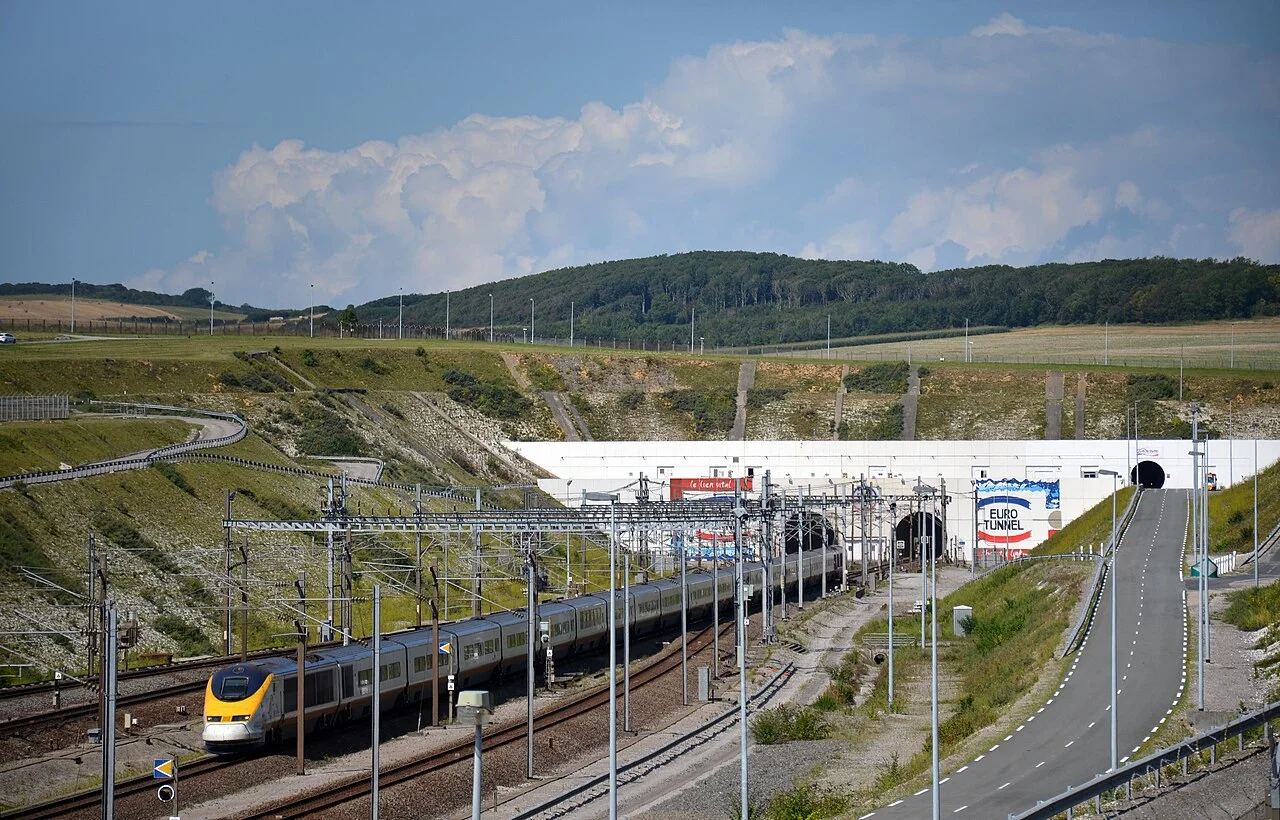
Cover image: Eurostar TMST train emerging from the Channel Tunnel at the French portal, Coquelles. Wikimedia Commons, CC BY-SA.

このコンテンツについて、さらに観点や背景を補足しましょう。

  • ログインするとコメントできます。